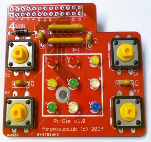
Soldering the 4tronix PiDie Kit

Click on any image to enlarge it

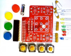
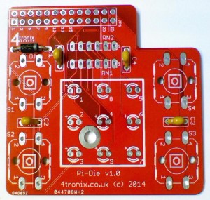
Check you have all the parts

pd00

  • Printed circuit board (PCB)
  • 1 x Diode (not shown above)
  • 4 x switches
  • 2 x resistor networks
  • 4 x capacitors 100nF
  • 12 x LEDs (2 x red, 2 x yellow, 2 x green, 2 x white, 1 x blue)
  • 1 x GPIO 26-waye female header
  • Mounting assembly (10mm hex spacer, 2 x M3 screws, 1mm washer)

Starting Soldering

If you haven’t soldered before, you might want to check out this instructable. I find that the following order of soldering works best, starting with the lowest profile components and moving to the highest. This allows me to place the components through the holes in the PCB, then turn the PCB over onto the desk surface and gravity will hold the components in place. You can also use Blutack to hold the components in place while you solder


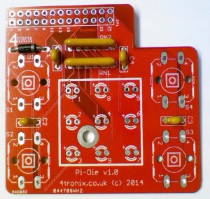
1. Add the diode

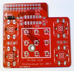
The black diode has a white/grey stripe on one end. this MUST match the marking on the PCB as shown in the photo below in the position D1

pd01


2. Add the 100nF Capacitors C1, C2, C3, C4

These are small, yellow and marked 104. It doesn’t matter which way round they are put in, but it is neatest if they point the same way. They fit into positions marked C1, C2, C3 and C4

pd02


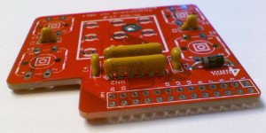
3. Add in the resistor networks RN1, RN2

These must be soldered in the correct way round. Double check before soldering. The writing needs to be closest to the GPIO header location, with the black dot (for pin 1) next to the end marked on the PCB with a small ‘1’

pd04 pd03


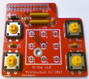
4. Solder the switches

These may already be clipped into position when you receive the kit, because that protects them during shipping. However, they will not be soldered so you need to do that for them to work. It doesn’t matter which way round they go – they can fit in 2 positions.

pd05


5. Add in the LEDs

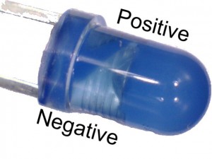
The LEDs must fit in the correct way round or they will not work. The long legs on each diode must go into the hole next to the + mark on the PCB. All LEDs are oriented the same way – so if you get one right, then all should be right.

Step04 led01 pd06


6. Solder the GPIO Header

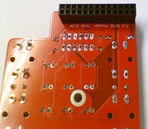
This must be placed on the opposite side of the board to all other components. It is extremely difficult to remove them if soldered incorrectly, so please double check before soldering

pd07


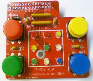
7. Add the Caps for the switches

These can go any way round, Just carefully push on so they click in place

pd08


8. Screw on the spacer

Fit an M3 screw through the hole in the board, then add the 1mm washer, then screw on the 10mm hex spacer. You can then push the board onto the Pi and the spacer will keep the board stable when the switches are pressed. You can screw it onto the Pi if you like, or simply let it rest. Please don’t use this spacer if using a Rev A Pi (without the mounting holes) as there are components in that place which can be damaged,

4tronix Initio Home Page

About 4tronix Initio

IMG_0277a

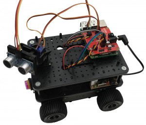
The Initio 4WD robot platform has been specially designed here in the UK to work easily with Arduino and Raspberry Pi controllers. Supporting products include motor driver boards, sensor shields, sensors, pan-tilt mechanisms and more. We also have a range of kits available for both Arduino and Raspberry Pi platforms

Outline Specification

  • An extremely flexible and easy to use 4WD Robot platform designed by 4tronix especially for Raspberry Pi and Arduino
  • Injection moulded from tough ABS
  • Built-in powerful 170-size motors and high-quality gearboxes
  • Arduino (UNO, Mega2560 or Leonardo) and Raspberry Pi mount directly onto the base-plate
  • 6-cell battery box with switch, charging socket, wiring for motor driver and Arduino already in place
  • Built-in speed encoders on each side with electronics already fitted
  • Each wheel can be individually decoupled from the gearbox – run as 1WD, 2WD or 3WD if you want!
  • Fixings for stepper motors (28BYJ-48 as found in our shop – not included) so you can replace the DC Motors with stepper motors for greater accuracy
  • No soldering or gluing required – simply screw together and plug in the wires (of course you can add things we haven’t thought of and they may need soldering)
  • The main chassis is delivered ready-built and all wires connected
  • All you need to do is add in the control boards and screw on the top plate
  • Mounting plates included for IR obstacle sensors and Line sensors
  • Loads of extra mountings for additional boards included


Purchasing Initio

4tronix Initio Assembly


Online Guides:

Other Assembly Information

Downloadable PDF Guides:


TroubleShooting

Motors Not Turning

  • For Raspberry Pi, ensure you are using correct software. Use the software in “robohat” folder if using RoboHat, or in “initio” folder if using Pirocon
  • Batteries. You must use good quality rechargeable batteries, not alkaline. We strongly recommend Energizer Extreme 2300mAH


4tronix Initio Programming Examples

Arduino

Arduino examples are found in our Arduino support site

  • initio_01 simply moves initio back and forwards and spins
  • initio_02 uses PWM to control the speed and create smooth turns
  • initio_03 shows how to use the speed sensors to move accurate distances
  • EncoderTest01 tests the operation of both wheel sensors. Use the switches on the top of the gearbox to disengage the wheels from the gears, then turn the wheels by hand to see the results on the serial monitor
  • initio_04 uses the obstacle sensors to avoid obstacles
  • initio_05 adds a light-follower function using LDRs mounted on the Pan/Tilt (Connect one end of each LDR to 0V, the other ends to A0..A3)
  • initio_06 uses the line sensors to follow a black line and stop when it reaches a cross-roads
  • initio_07 uses the ultrasonic sensor mounted on the Pan/Tilt to avoid obstacles and travel in the direction of most space


ScratchGPIO

Raspberry Pi ScratchGPIO examples are found in our GitHub

  • MotorTestB.sb    Allows control of the motors using arrow keys (ScratchGPIO)
  • PanTiltTest.sb    Allows moving the pan/tilt assembly using arrow keys (ScratchGPIO)
  • UltraSonicTest.sb    Shows operation of the UltraSonic sensor (ScartchGPIO)
  • TrackerTest.sb    Uses the ultrasonic sensor on a Pan/Tilt assembly to follow (ScratchGPIO)
  • Avoider.sb    Uses IR obstacle sensors and motors to avoid objects (ScratchGPIO)
  • InitioTest.sb    Uses line sensors, obstacles sensors and motors (ScartchGPIO)
  • Also see this post for using the wheel sensors with Raspberry Pi and the PiRoCon

Python

Raspberry Pi Python examples can be downloaded from an LXterminal session and connected to the internet, type in or copy and paste:.

wget https://4tronix.co.uk/robohat.sh -O robohat.sh

Then type in:

bash robohat.sh

You will then have a number of python examples in the robohat folder to try. Run them with:

sudo python filename.py
  • motorTest2.py:  use the arrow keys to move forwards and backwards, spin left or spin right. Space to stop. Use . and , to increase or decrease speed
  • sonarTest.py: Prints the distance in centimetres from the ultrasonic sensor, once every second
  • irTest.py: Prints the state of the IR line and obstacles sensors, every time the state changes.
  • servoTest.py:  use the arrow keys to pan and tilt

NB. If using the older Pirocon controller the replace robohat with initio throughout the above.

 C

Yes, you can now program the Initio for Raspberry Pi directly in C. What’s more, it works seamlessly with both the Pirocon and the RoboHat control boards so your program can work on either without being changed

Visit this link to find out more about this which was written by Dr Raimund Kirner at the University of Hertfordshire


PiRoCon Robotics Controller – Links

Links for Various Resources for the 4tronix PiRoCon


*** READ THIS NOW! VERY IMPORTANT ***

If you are experiencing low power to the motors when using the DC Jack input, it is very likely that you have not set the power selection jumper correctly to the right as shown below:

pc04a


New: PiRoCon v2 released


Errata

  • Pins 15 & 16 (Broadcom GPIOs 22 and 23) are swapped from what is shown on the silk screen
  • Pin 11 is shown as GPIO 07 on the jumper bank, instead of GPIO 17


Getting to Know Your PiRoCon

Tour of PiRoCon

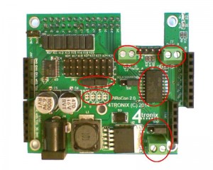
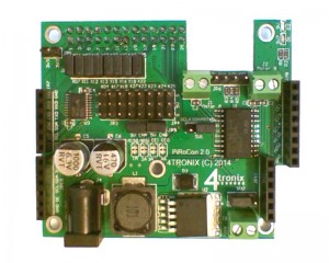
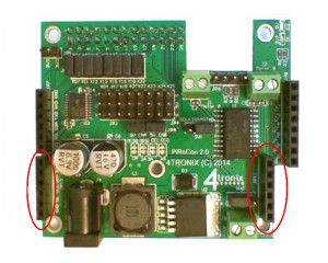
In this post we will take a tour around the PiRoCon v2 board and see how all the various elements operate and can be configured

pc01a


Power Supply

pc03a

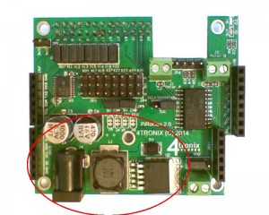
  • The DC Jack (bottom left) is the input connection for your battery voltage. The voltage should be between 7V and 12V and will need to be able to supply at least 2A. This is a 2.1mm DC Jack with positive centre pin. Below about 6.5V, the regulator will not be able to output the 5V required for the Raspberry Pi to work. Above 12V, the regulator will probably get too hot.
  • The voltage regulator (lower left side) is used to convert the input voltage to 5V as required by the Raspberry Pi. For version 2 of PiRoCon we use a switching regulator which barely gets warm even at higher input voltages and no heatsink is required. Note that the motors are not powered from the regulated power supply


Motor Drivers

pc04a

  • The terminals for two DC motors are at the top right of the board. Motor A on the left and Motor B on the right
  • Both terminals are wired the same way (left to right) so the same inputs would drive the motors in the same direction. If you use one motor for a left side drive on a robot and the other for a right side drive, then you should swap the wiring for the second motor. For instance, using the example programs on the Initio, you should wire Red-Black-Black-Red
  • The motor terminals are driven directly from the output of the H-Bridge driver chip L293DD (shown just below the motor terminals)
  • The 4 GPIO pins used to drive the chip are the SPI pins CE0, CE1, MISO and MOSI. These are connected via solder jumpers (to left of the L293D) – these are pins 19, 21, 24, 26
  • If you want to use other pins to drive the motors, then you should cut these these connections and wire your own connections to the required positions
  • Each motor has an enable pin which by default is connected directly to 5V using the jumpers just above the solder jumpers and below the 8×3 header block. For some purposes it is better to use the enable pins for the PWM signal, so that you can use the 4 control pins to purely control the direction. If you want to do that, then you should remove the jumpers and wire the enable pins to a PWM source (eg. an Adafruit 16-channel PWM board plugged into the PiRoCon expansion sockets)
  • In the bottom right of the photo above is a separate 2-pin terminal for external power. If you don’t want to drive the motors from the incoming battery voltage on the DC jack, you can move the selection jumper (just above the 2-pin terminal) and provide your motor voltage directly to the 2-pin terminal. This voltage can be from 5V-15V DC – ensure you connect it the correct way round. Note that this 2-pin terminal does NOT power the 5V regulator, only the motors.
  • For normal operation using the DC jack input. ensure the jumper is placed to the right side, or no power will get to the motors


5V GPIO Connector (8×3 rows)

pc05a

  • NOTE: The Ground pin for the 8×3 block of GPIO pins is at the lower side for v2 PiRoCon (upper side for v1), so be careful when wiring
  • There are 8 unallocated GPIO pins available and these are brought out to a bank of 8×3 male headers
  • The headers are at 0.1″ pitch so you can connect standard 3-pin 5V sensors or servos etc. directly to them
  • Each signal is separately fed through a bidirectional level converter so can safely be used to input or output at 5V
  • Each signal is labelled with an x-number (on the jumper block) and a #-number
    • x refers to the physical pin number on the GPIO connector. So the first signal on the left is x07 which is pin 7 on the GPIO connector
    • # refers to the GPIO number itself. So the first signal (x07) is GPIO#04
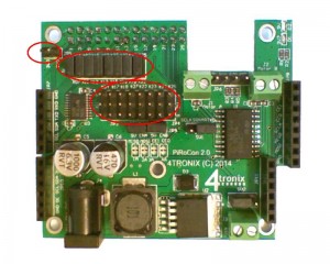
  • Each signal can be disconnected from the GPIO header to the Raspberry Pi, by removing the relevant 2-pin jumper (shown top left)
    • If you remove the jumper, then the related signal in the bank of 8×3 is no longer in use
    • You should then connect a 3.3v max input or output to the signal pin where the jumper was
    • This allows the use of 3.3V sensors (eg. the wheels sensors on the Initio)
    • There is a 2-pin header (top left) which has two 3.3V connections, intended for powering 3.3V sensors
  1. #04 – x07
  2. #17 – x11
  3. #18 – x12
  4. #27 – x13
  5. #23 – x16 NB. Labelled incorrectly on board as #22
  6. #22 – x15 NB. Labelled incorrectly on board as #23
  7. #24 – x18
  8. #25 – x22

Please note, as described above, there is a layout mistake on the PCB which results in pins 15 and 16 (GPIO numbers 22 and 23) being swapped. So ensure that you plug into the correct connection for your application

Ultrasonic Sensor

pc06a

  • There is a group of 4 pins (shown above at top right) that are designed to add an HC-SR04 ultrasonic sensor directly to
  • From the left, these are 5V, Trig, Echo, Gnd and match the ordering of the pins on the sensor
  • There are 3 resistors which process the signals so that both Trigger and Echo can use the same GPIO pin on the Raspberry Pi and also that this is 3.3V safe
  • The jumper (just below and left of the ultrasonic 4-pin connector) can be used to select either TXD (pin 8) or SCLK (pin 23)
  • If you want to use a completely different pin, simply remove the jumper completely and connect the pin you want to use to the centre pin of these 3


SPI Connector

pc07a

This 8-pin female header allows you to connect the SPI signals. Note however that these are also used for motor controls by default, so you may need to attach the motors to different pins if you want to use SPI. Alternatively, simply don’t connect the motors when using SPI.

  1. 5V
  2. 3.3V
  3. CE1
  4. CE0
  5. SCLK
  6. MISO
  7. MOSI
  8. GND


I2C Connector

pc08a

This 6-pin female header allows you to connect additional modules using the I2C connections. These are not used on the PiRoCon itself, although the expansion boards (see below) can use them. This connector also has the UART RXD/TXD pins on together with Gnd and 3.3V

  1. Gnd
  2. RXD
  3. TXD
  4. SDA
  5. SCL
  6. 3.3V


Expansion Board Sockets

pc09a

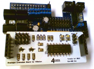
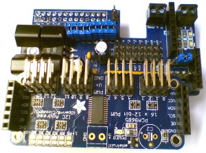
There are two 6-pin expansions sockets that use I2C connections to add functionality to the PiRoCon. Expansion boards available right now are:

  • 4-channel analog input (ADC) with single channel analog output (DAC) from 4tronix

tour_exp01


  • 16-channel PWM or servo driver from Adafruit

tour_exp02


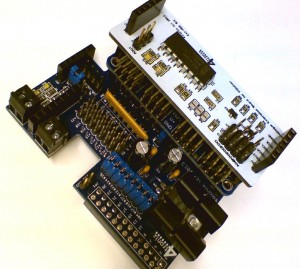
If you use stacking headers for the 6-pin connectors, and right-angle headers for the signals on the boards, you can stack these I2C expansion boards as much as you like. Here are both the above expansion boards fitted:

tour_exp06


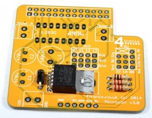
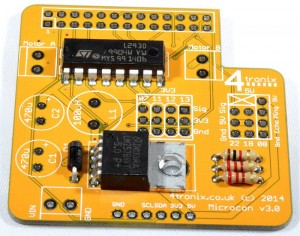
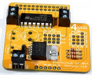
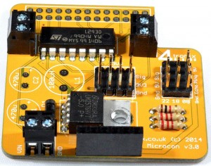
MicRoCon mini Robotics Controller Board for Raspberry Pi – Assembling

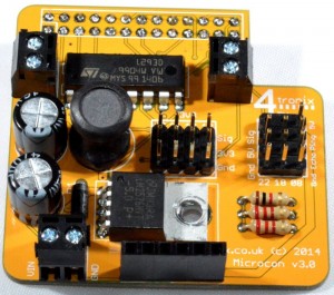
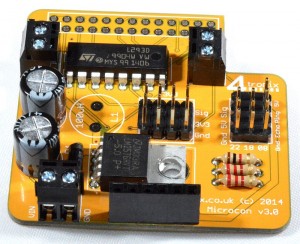
MicRoCon Robotics Controller Kit

Microcon3_01a


Click on any image to enlarge.

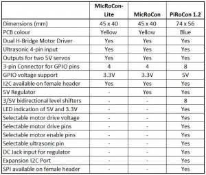
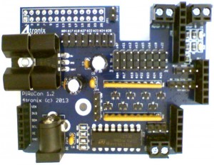
The MicRoCon is the baby sister to the more powerful PiRoCon board, but incorporates many of the same features and in fact can use exactly the same code for programming as the pins it shares are the same. Here is a brief comparison table between the controllers:

Comparison

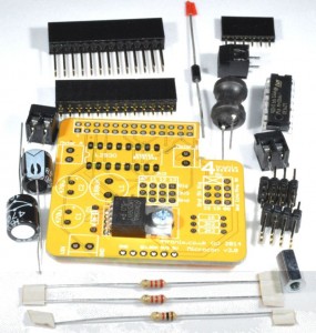
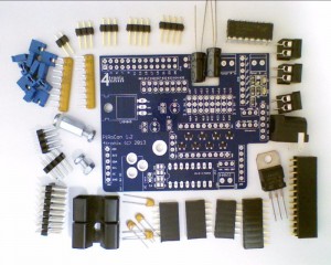
Check you Have all the Parts

Microcon3_00b

  • Printed Circuit Board (PCB) with the 5V regulator already fitted
  • L293D H-Bridge driver chip
  • 470uF capacitors x 2
  • 100uH Inductor
  • Diode
  • 2-pin Screw Terminals x 3
  • 2K2 resistors x 2 (coded Red-Red-Red-Gold)
  • 1K resistor (coded Brown-Black-Red-Gold)
  • 4×3 male header blocks x2 (one has 2 pins removed) [alternatively we may ship with 4 off 2×3 male header blocks depending on availability]
  • 6-pin female header
  • 26-pin GPIO header
  • Fixing hardware – M3 screw, M3 nut
  • Heatsink
  • Rubber “foot”


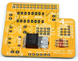
Starting Soldering

If you haven’t soldered before, you might want to check out this instructable. I find that the following order of soldering works best, starting with the lowest profile components and moving to the highest. This allows me to place the components through the holes in the PCB, then turn the PCB over onto the desk surface and gravity will hold the components in place. You can also use Blutack to hold the components in place while you solder


1. Add the Resistors

The PCB is labelled with the resistor values. 2K2 resistors are marked by Red-Red-Red-Gold bands, and the 1K resistors is Brown-Black-Red-Gold. It is neatest to ensure that all resistors point the same way. Make sure you snip off the leads on the back after soldering.

mcStep01a

2. Add the Diode

The PCB is labelled with the resistor values. 2K2 resistors are marked by Red-Red-Red-Gold bands, and the 1K resistors is Brown-Black-Red-Gold. It is neatest to ensure that all resistors point the same way. Make sure you snip off the leads on the back after soldering.

mcStep02a

3. Add the L293D chip

Make sure that pin 1, marked by the little black round indentation and the U-shaped cutout of the chip, is at the edge of the board as shown below.

Note: This chip may already be inserted in the board for protection during transport – but it won’t be soldered.

mcStep03a

4. Add the screw terminals

These terminals are used to connect the motors and also to supply external power to the board for the regulator and the motor driver.

Solder all the terminals onto the PCB facing outwards

mcStep04a


5. Add the Male Header blocks

These 4×3 header blocks are slightly different from each other, as one has 2 pins removed from it. Make sure you put them into the correct place as they would be difficult to remove if placed incorrectly (of course the block with all its pins won’t fit into the other position, but vice versa is possible).

mcStep05a


7. Add the 6-Pin Female Header

This header brings out the I2C pins from the Raspberry Pi together with 5V, 3.3V and Ground. This is our standard layout and the 4tronix IP Display dongle will fit directly in here.

mcStep06a


8. Add the 470uF Capacitors C1 and C2

These are polarised and must be placed the correct way or magic smoke will appear. The long lead is positive and should be placed in the hole marked with a ‘+’ on the PCB. The casing has a grey band with down arrows next to the negative pin – the grey band should be facing the GPIO connector as shown below. Cut off the legs on the underside after soldering

mcStep07a


9. Solder the GPIO Connector to Bottom of PCB

Your kit may be provided with a choice of standard or extended header – select the one you want to use. The other is not required. Make sure you solder this to the correct side of the board!

mcStep08c


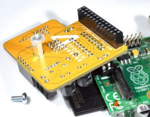
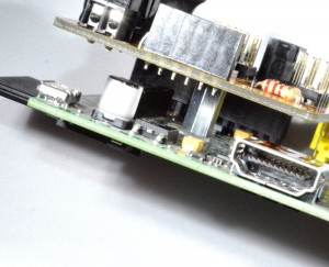
11. Finally Fit the Pillar and rubber foot, then fit onto the Raspberry Pi

mcStep12a   mcStep13a  mcStep14a  mcStep15a


Return to MicRoCon Home


Assembling and Using PiRingo

Purchase 4tronix PiRingo >here<

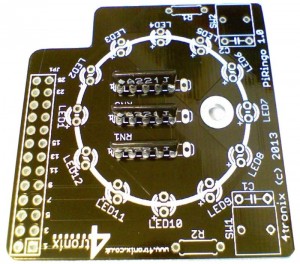
Parts Included

  • Blank PCB
  • 12 LEDs – various colours depending on design chosen
  • 3 resistor networks (5-pin)
  • 2 miniature tact switches (2-pin)
  • 2 capacitors (100nF) – optional
  • GPIO connector header
  • 11mm hex spacer and screws (10mm metal spacer plus 1mm washer)


Tools Required

  • Soldering iron
  • Side cutters (could use nail clippers if necessary)


Soldering Sequence

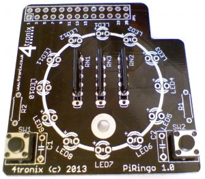
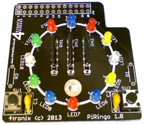
  1. First add the 3 resistor networks to positions RN1, RN2 and RN3 as shown below. These are black, labelled A221J and have a white dot near one end. The white dot must be at the pin marked with a ‘1’ and next to the component name (ie. RN1, RN2 and RN3)
    step01
  2. Note that an unused hole is left at the other end (this hole is to allow different components to be used if 5-pin networks become unavailable for any reason)
  3. Then add the 2 switches, one either side in positions SW1 and SW2. It doesn’t matter which way round these are placed
    step03
  4. If you are concerned about switch bounce you can add the two 100nF capacitors, C1 and C2. As they are included with the kit and not difficult to add, then we recommend that they are added. it doesn’t matter which way round they are fitted
  5. Then add the LEDs. These are all the same way round with the long lead next to the ‘+’ on the PCB. The LEDs will not work if they are connected the wrong way round, but no damage will occur. You can also tell the negative lead by looking inside the LED itself. The lead with the large triangular plate is the negative lead.
    Step04led01
    step05
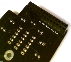
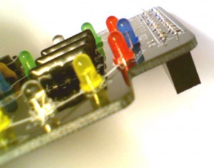
  6. Finally add the GPIO connector. This must be added to the opposite side of the board!
    step06astep06b


Using the PiRingo

  1. Download example Python codes from our GitHub
  2. You can also view the PCB design schematic at the same location
  3. Download and install the Scratch GPIO v4 from @cymplecy
  4. Current example Python programs are:
    1. allon.py – switches all LEDs on
    2. alloff.py – switches all LEDs off
    3. flashdemo.py – goes through a sequence of flashing and chasing patterns. These are all coded as separate functions, so you can easily change to any sequence you require
    4. swing.py – moves a single LED under command of the two switches. See who can press the  switches faster
    5. swing2.py – creates a range of LEDs for the fastest switch presser – when the bar reaches the other side, the winner is declared with flashing lights!
  5. Current example Scratch GPIO programs are:
    1. Traffic lights simulation


Pin Definitions

The Pin numbers below refer to the physical pin numbers on the GPIO header. To use these pin numbers in Python, be sure to set the GPIO mode as “Board” as shown here:
GPIO.setmode(GPIO.BOARD).

All LEDs and switches are Active Low. So set an LED to 0 to turn it on, set to 1 to turn it off. Switches are 0 if pressed, 1 if not pressed

  • LED1 – pin 7
  • LED2 – pin 11
  • LED3 – pin 12
  • LED4 – pin 13
  • LED5 – pin 15
  • LED6 – pin 16
  • LED7 – pin 18
  • LED8 – pin 22
  • LED9 – pin24
  • LED10 – pin26
  • LED11 – pin 8
  • LED12 – pin 10
  • Switch 1 – pin 19
  • Switch2 – pin 21


Assembling Initio Robot using PiRoCon Controller

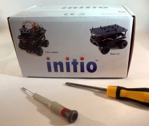
build01Initio in box and philips head Screwdrivers

These are all the tools you will need to complete the robot.

You may also want a pair of side-cutters to remove some of the extra mounting


Hbuild02ere’s what is in the box
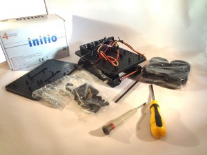
Main chassis with motors, gearbox, battery box and wiring

Top plate

Bag of plastic parts: pillars, standoffs, offset standoffs

Various screws

4 wheels with “SuperGrip” treads
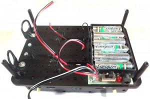


build03Step 1: Add the vertical pillars by screwing from underneath with the wide-head screws

It’s a good idea to add the mounts for the obstacle sensors and line sensors if you have them.


Step 2: Screw the top plate on using the remaining 4 wide-head screws.

build04a

The pillars marked with red circle are where the Model A/B Pi will mount

For a Model A/B you will need to snip off some of the unused pillars so they don’t touch components on the Pi, but this is not necessary for a B+ if you use the adaptor plate

Feed the wires for the motors up to the top


Step 3: For Model A or Model B Sbuild05crew the Pi into position with 2 screws.
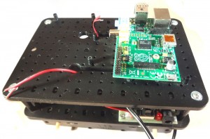
If you have used the correct mountings then the Pi will have the SD card slot above the On/Off switch

For most purposes you can use a Model A as easily as a Model B.
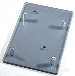


converter01a


Step 3: For Model B+

Use the included adaptor plate (Only for Initio shipments after 20th September 2014). You should screw the 4, 10mm pillars into the plate using 4 of the screws provided, then screw the plate to the Initio using the same holes as for a ModelA/B. There is no need to snip any mountings off in this case.


Alternatively (also for shipments before 20th September 2014) you can use 1 fixed mounting for the top right hole, and use one of the small offset mounts for the bottom left hole. You will need to snip of some of the mountings for this arrangement.
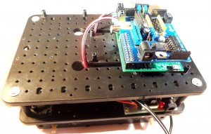


build06Step 4: Now attached the PiRoCon by pushing carefully onto the GPIO header. If using a Model B+ with Pirocon v1 then you will need to attach the extended header (provided) to the PiRoCon before plugging into the Pi. You should also use the 12mm male-female hex pillar to extend the pillar length to match. For Pirocon v2 it will fit directly to the Model B+. All other instructions remain the same

Ensure that all pins are plugged in correctly as damage will ensue if you plug it in wrongly

Use the 10mm hex spacer and 1mm washer provided to allow the PiRoCon to rest securely on top of the Pi’s mounting screw

An alternative when using a Raspberry Pi Model A/B is to use a Male-Female hex spacer. Screw the male end through the Pi and into the mounting pillar (you will need to drill this to 3mm). Then you can fit the 1mm nylon washer and screw the PiRoCon onto the pillar. It is all mounted firmly and can only be removed with a screwdriver.
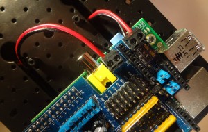


build07Step 5: We can now attach the motor wires to the PiRoCon terminals

Motor A for the left motor and Motor B for the right motor

The wires are colour-coded so that we know which way is forwards. The correct order is Red-Black-Black-Red as shown below. (note that “black” is actually a “black and red” wire)


This can be tested with the MotorTest script at this point if you like.


build09Step 6: Attach the Pan/Tilt assembly

Head on over to >here< for the assembly instructions if you haven’t already built the pan/tilt assembly

The ultrasonic sensor is attached to the clip-on pan/tilt mount by the included small saddle clamp and small screws. In fact the saddle clamp is designed to clamp the 30cm female-female cables, enabling the sensor to be plugged and unplugged at will. You will have received the correct number of wires, but they may not be the same colours. Remove 4 wires from your strip of 10 (for most kits).


Test with the UltrasonicTest script
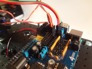


build10Step 7: Plug in the servos for the Pan/Tilt assembly

Pan servo is attached to x22/#25 on the PiRoCon board. Tilt servo is attached to x18/#24

Be very careful to ensure correct orientation of the servo connector or the servo will be damaged. The Brown wire is Ground and should be connected to the pins marked G. Orange wire is signal and should be connected to a pin marked S.  Note that Pirocon v2 has the G pins near the centre of the PCB, while v1 has the G pins nearest the edge.

The ultrasonic cable should be plugged into the 4-way male header matching the signals on the sensor: 5V – Trig – Echo – Gnd with 5V nearest centre of PiRoCon board and Gnd nearest the edge. All these are marked on the PCB – just be careful.


Test with the PanTiltTest script or the Tracker script


Step 8. Adding Line Sensors and Obstacle Sensors

This is enough to test most of the system. You can now add line sensors and obstacle sensors if you have them. You can attach these to any of the 6 remaining 3-way positions. Reading the sensor on the selected pin can be done in Scratch GPIO or Python very simply using the Pin or GPIO number labelled next to the connectors chosen.


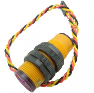
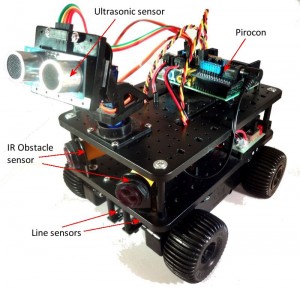
Obstacle Sensor: These are fitted at the front of the Initio, through the round mountings. Point one slightly left and the other slightly right. They come with ready-made cables so can be attached directly to the PiRoCon. Again, ensure that the Black wire is connected to a pin marked G (for Gnd) and the Yellow wire is connected to a pin marked S (for Signal) on Pirocon.
IRSensor03

NOTE: It appears that a batch of these has been shipped with only one mounting collar per sensor. Please contact us if you don’t have 2 per sensor and we will ship the other. While waiting for the missing collars you can fit the sensors loosely in the mounting brackets and still operate them successfully.


Line sensor: These are mounted on the end of the 40mm black pillars so that each sensor is about 1cm above the ground. Use the long Female-Female cables to connect them to the PiRoCon.

We find it is best to use the hole nearest the middle of the sensor for mounting them, but it’s up to you.

line01


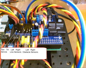
For example software we’ve created, we have used the following connections for Line and Obstacle sensors:

  • Left Line sensor: x12/#18
  • Right Line sensor: x13/#27
  • Left obstacle sensor: x07/#04
  • Right obstacle sensor: x11/#07

wiring03 wiring01


PiRoCon Motor Power setting

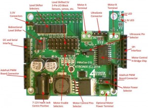
When using the DC jack from the Initio to power the PiRoCon, you should ensure that the motor power selector jumper is nearest the edge of the board as shown in the bottom right of the photo below:
pc02c


The Completed Ultimate Kit looks like this:
initult01c


NB: At this point you will have 3 cables remaining:

  • 2 cables with 4 wires each: Red, Black, Orange, Brown. These are the wheel sensors and it is recommended not to bother with these until you are fully familiar with the system
  • 1 cables with Red & Black wires from the switch board. This is an alternative for the DC jack power cable and is not required for the PiRoCon. Other controller boards have 2-pin screw terminals which you would use this cable with. Ensure that the 2 ends of this cable to not short against each other or anything else


Connecting Wheels Sensors from Initio

The level shifters on the Pirocon are not compatible with the outputs of the wheel sensors, so you must use the wheel sensors at 3.3V and connect the output(s) directly to the GPIO pins. To do this with Pirocon:

  • Remove the blue jumpers from the pin(s) you want to use from the block of 8 jumpers.  Let’s use #22 and #23
  • Connect the Black wire from each wheel sensor to a suitable Gnd pin – you could use the grounds for #22/x15 and #23/x16 as these are not being used otherwise
  • Connect the Red wire from each wheel sensor to a 3.3V connection – there are 2 pins near the pin 25 end of the GPIO connector for this purpose
  • Connect the Orange (or Brown) wire from each wheel sensor to the pins marked #22 and #23 (where the jumpers were removed)
  • You can now read these two pins to get 18 pulses (36 edges) per revolution of each wheel
  • If you additionally use the Brown wires from each sensor (you will need to use 2 more pins and remove 2 more jumpers) you can get additional, out of phase, readings for each wheel. This allows you to determine the direction of travel of each wheel as well as speed. When you detect an edge on one signal, then the level of the other signal will tell you which direction the Initio is going


<< PiRoCon Connection Details

PiRoCon Robotics Controller for Raspberry Pi – Connect & Use

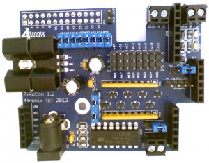
PiRoCon Robotics Controller

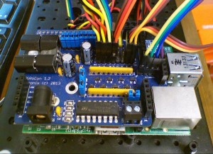
NB. V1.2 PiRoCon controller is now shipping. This has a few minor changes and needs to use the addon name “PiRoConB” in Scratch GPIO 4 onwards to work correctly.

Nomenclature

All connections are referenced by the pin number on the GPIO connector. Most also show the name of the signal as normally used on the Raspberry Pi. For instance GPIO connector Pin7 is called GPIO#04. As there is not much space on the PiRoCon board, we have labelled the 8 free, level-shifted, GPIO pins with an ‘x’ prefix to indicate the GPIO pin number, or a ‘#’ prefix to indicate the GPIO number. So the first pin is x07 (#04).

Connector positions

The following drawing shows the position of the major connector blocks. Note especially:

  1. Row of eight 2-way male header pins with jumpers to feed the “unallocated” GPIO pins into the level shifters – remove the jumper to disable if required
  2. Row of eight 3-way male header pins. The pins nearest the edge of the board are Ground, the middle row is +5V and the pins nearest the centre of the board are the signal pins
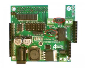
  3. Row of four male header pins. This is where the HC-SR04 ultrasonic sensor can be attached. Ground nearest the edge of the board, then Echo, Trigger and +5V (Vcc) in that order
  4. Use the three pins with a single jumper to select which GPIO pin to use for the ultrasonic. Note the error on the silk screen. The pin marked Tx is in fact pin 23, and the pin marked SCL is in fact Pin 8
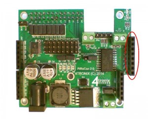
  5. The screw terminal Motor A is intended for the left-side motor(s) and Motor B for the right-side motor(s)
  6. Motor A uses pins 26 and 24 – Scratch GPIO uses 26 as the direction control and 24 as the PWM speed control (for PiRoCon 1.0 this was pins 26 and 21)
  7. Motor B uses pins 21 and 19 (Scratch GPIO uses 21 as the direction control and 19 as the PWM speed control (for PiRoCon 1.0 this was pins 24 and 19)
  8. Servo A (Tilt) is on pin 18 and Servo B (Pan) is on pin 22 (these are the right-most connectors on the 8×3 block
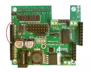
  9. the two 6-pin female headers near the bottom edge of the board are for plugging in an Adafruit PCA9685 16-channel PWM controller. This is also supported in Scratch GPIO as Servo 1..16

prc01


Connecting Jumpers

  1. Assuming you require all 8 unallocated GPIO pins to use the bi-directional level shifters, then connect a jumper to every one of the 8 pairs of pins on the level shifter jumper block
  2. There is a 4-way header for the motor driver enable pins. For 2-pin driving of the motor, connect a jumper between the left two pins, and another jumper between the right two pins. (for 3-pin control of the motor, we would use a PWM output from the add-on Adafruit PCA9685 board to driver the enable pins. This has advantages for motor control, but is not used in the basic Scratch GPIO method)
  3. Connect the ultrasonic select jumper to either left-side (pin 23) or right-side (pin 8). Leave out this jumper if you want to use SCL/TXD for something else. You can then use a female jumper wire to connect the centre pin to your selected pin for the ultrasonic. All our examples use the jumper connected to pin 8 or pin 23
  4. The final jumper next to the Vin 2-pin terminal selects the power source for the motors. Connect to VBat to use the DC Jack battery input power, or connect to Vin to use the external screw terminal input (this has moved position and function since PiRoCon 1.0 where it was an unused jumper)


Connecting Ultrasonic sensor, Motors and Servos

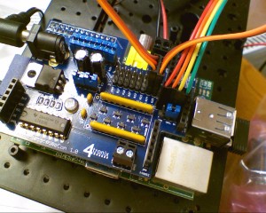
The photo below shows the motors, ultrasonic sensor and Pan/Tilt servos connected. Note the colours for the servos – it is important to get these the correct way around or you may damage the servos. For 4tronix pan/tilt kit, the colours are:

  • Brown: Ground (nearest edge of PiRoCon board)
  • Red: +5V (middle)
  • Orange:  Signal (inside pin)

Motor A screw terminal is connected to left-side motor. Motor B is connected to right-side motor.

Ultrasonic is connected directly: Gnd – Gnd, Trig-Trig, Echo-Echo, Vcc-5V

2013-10-23_0003


Connecting Wheels Sensors from Initio
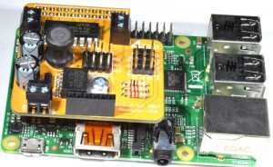
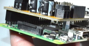
The level shifters on the Pirocon are not compatible with the outputs of the wheel sensors, so you must use the wheel sensors at 3.3V and connect the output(s) directly to the GPIO pins. To do this with Pirocon:

  • Remove the blue jumpers from the pin(s) you want to use from the block of 8 jumpers.  Let’s use #22 and #23
  • Connect the Black wire from each wheel sensor to a suitable Gnd pin – you could use the grounds for #22/x15 and #23/x16 as these are not being used otherwise
  • Connect the Red wire from each wheel sensor to a 3.3V connection – there are 2 pins near the pin 25 end of the GPIO connector for this purpose
  • Connect the Orange (or Brown) wire from each wheel sensor to the pins marked #22 and #23 (where the jumpers were removed)
  • You can now read these two pins to get 18 pulses (36 edges) per revolution of each wheel
  • If you additionally use the Brown wires from each sensor (you will need to use 2 more pins and remove 2 more jumpers) you can get additional, out of phase, readings for each wheel. This allows you to determine the direction of travel of each wheel as well as speed. When you detect an edge on one signal, then the level of the other signal will tell you which direction the Initio is going


Usage within Scratch GPIO

Note that this requires Scratch GPIO version 4 or later from SimpleSi

Commands available, in addition to the normal Broadcast pin11On, etc. are:

  • First you will need create a variable AddOn and set its value to PiRoConB (for v1.0 boards use “PiRoCon”)
  • Create a variable called MotorA (and MotorB), then set value from -100 to +100 for speed and direction. -100 is full speed reverse. +100 is full speed ahead. 0 is OFF
  • Create a variable Pan (and Tilt), then set values from -90 to +90. -90 is pointing left (or down (up??)),  +90 is pointing right (or up (down??)). 0 is pointing straight ahead

 << Assembling PiRoCon                                              >> Building Initio Robot with PiRoCon

PiRoCon Robotics Controller for Raspberry Pi – Assembling

PiRoCon Robotics Controller Kit


Features

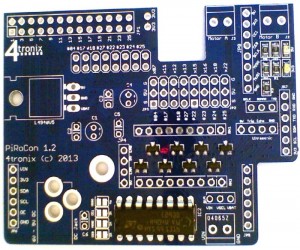
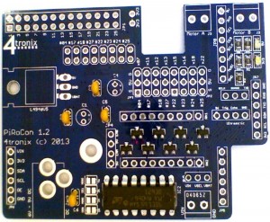
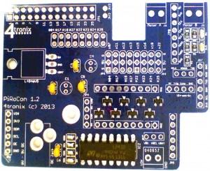
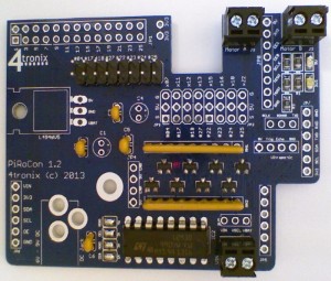
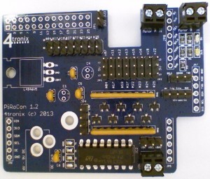
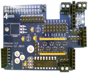
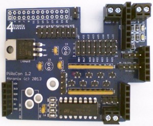
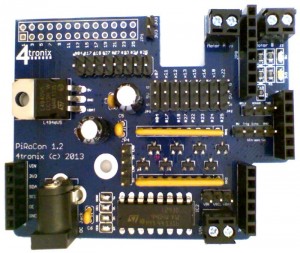
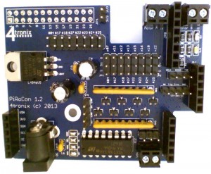
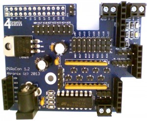
The PiRoCon is a controller board for motorised robots. It plugs directly on top of a Raspberry Pi and can be firmly attached using the included pillar and screws (Rev B Pi only). It is designed specifically to drive the 4tronix Initio robot, but it is flexible enough to be used with many different types of robot. Scratch software support is provided by the excellent Scratch GPIO Handler from @cymplecy – Version 4 or later required.

prc19

Click on any image to enlarge

The PiRoCon Robotics Controller board includes:

  1. 5V regulated power supply for the Pi, the board itself and any attached peripherals
  2. All 8 un-allocated GPIO pins brought out to 3-way headers with power, ground & signal for sensors, etc.
  3. All of these GPIO include bidirectional, 5V – 3V3 level-shifters
  4. 2 of these pins can be used to drive standard servos (used on Initio to control the Pan/Tilt mechanism)
  5. Level-shifters can be removed, or allocated to different pins by removing jumpers and replacing with jumper wire
  6. A dual H-Bridge is included, connected to to bi-directional PWM controlled motors on screw terminals
  7. The H-Bridge is connected by default to pins 19, 21, 24 and 26, but can be changed
  8. A 4-pin connector for the cheap HC-SR04 Ultrasonic range sensor. This is fed, via a resistor network, to a single pin which is jumper selectable between pins 8 or 23
  9. SPI female header for the SPI pins
  10. I2C/UART header for the I2C and UART signals
  11. Red LED for 5V, Yellow LED for 3V3
  12. Connectors to allow plugging on the Adafruit 16-Channel Servo/PWM Driver using PCA9685 chip. This optional add-on allows PWM control of up to 16 additional servos, or brightness control of 16 LEDs, etc. You can even use 2 of these hardware PWM pins to control the dual H-Bridge using 3 pin mode (where 2 pins control motor direction and the 3rd PWM pin controls speed)

And here is a brief comparison between the PiRoCon and the MicRoCon (his baby sister)

Comparison

Check you have all the parts

The PiRoCon is delivered as a kit with the following parts. We also offer a soldering service should you want us to solder it for you

prc01

  1. PCB
  2. All surface mount components are ready-assembled
  3. 3 off 6-pin female headers
  4. 1 off 8-pin female header
  5. 1 off 26-pin GPIO header
  6. 1 off 3×8 male header
  7. 2 off 2×4 male headers
  8. 12 off 0.1″ jumpers
  9. 2 off resistor networks
  10. 4 off 100nF ceramic capacitors
  11. 2 off 47µF electrolytic capacitors
  12. L4940V5 low drop-out 5V voltage regulator
  13. L293D dual H-Bridge motor driver
  14. 3 off 2-pin screw terminals
  15. DC Jack socket
  16. 10mm hex pillar with 2 screws and 1mm thick washer (total 11mm required between boards)
  17. Heatsink with mounting screw and nut


Assembling Process

Starting Soldering

If you haven’t soldered before, you might want to check out this instructable. I find that the following order of soldering works best, starting with the lowest profile components and moving to the highest. This allows me to place the components through the holes in the PCB, then turn the PCB over onto the desk surface and gravity will hold the components in place. You can also use Blutack to hold the components in place while you solder


1. Add the L293D Motor Controller Chip

Make sure that pin 1, marked by the little black round indentation and the U-shaped cutout of the chip, is at the edge of the board as shown below

prc02


2. Add the 100nF Capacitors C2, C3, C5 and C6

These are small, yellow and marked 104. It doesn’t matter which way round they are put in, but it is neatest if they point the same way. They fit into positions marked C2, C3, C5 and C6

prc03


3. Solder across the Motor control pin selections

There are 4 solder bridges to be made. These lie between pin 1 of the L293D chip and capacitor C6. Make sure these are cleanly bridged with no solder traces shorting anything out. If you want to change the pins used to control the motors, then you should remove the solder bridges and connect them to the pins of your choice.

prc04


4. Add the Resistor networks RN1 and RN2

These are long and orange. They are polarised and must be connected the correct way round or the level shifters will not work. There is writing on one side only – this writing should be away from the L293D. The dot at one end is pin 1 and this should be in the square at the end of the silk screen markings

prc05


5. Solder 2-Pin screw terminals

These are for the motor connections (Motor A and Motor B), and for the alternative source of power for the motor driver – Vin. Make sure you fit them with the screw terminals facing outwards

prc06


6. Add the Male header blocks: 8×2 and 8×3

The 8×2 header block is actually made from 2 of the 4×2 headers

prc08 prc07


7. Add the Male single row headers

There are five of these individual single row headers and are probably the trickiest items on this board to solder neatly:

  • The 2-pin header is used for the 3.3V near the GPIO header positon
  • One of the 4-pin headers is used for motor enables. The purpose of these is so that you can connect the enable pins for each motor output to a PWM pin as this is the better way to control motors, rather than use PWM on one of the drive pins. The reasoning is fairly esoteric and really makes little difference in practice. But as with many things on the PiRoCon, we provide the option for the customer to experiment
  • The other 4-pin header is to connect a 4-pin ultrasonic sensor HC-SR04 directly. All signal condition and converting to single pin operation is provided on the PiRoCon board
  • One 3-pin header is used to select which GPIO pin is used for the ultrasonic sensor: Pin 8 or 23
  • The other 3-pin header is next to the Vin terminal and used to select whether the battery voltage (VBat) or the screw terminal input voltage Vin is used to power the motors. If you want to power the Raspberry Pi yourself and not use the onboard regulator, you can simply change this jumper to connect to Vin and not use the DC jack battery input

prc09


8. Add the Female headers JP5..JP8

There are 4 female headers; 3 are 6-pin and 1 is 8-pin

  • JP5 and JP6 (both 6-pin) are used for the I2C expansion port. You can plug Adafruit’s 16-channel PWM board directly in here. Also the 4tronix ADC/DAC board and other boards are planned for the future
  • JP7 (6-pin) is the general purpose I2C expansion that also carries the RXD and TXD serial pins
  • JP8 (8-pin) contains the SPI pins
  • All 4 headers have 5V, 3.3V and Gnd available

prc10


9. Solder the voltage regulator

The L4940V5 is a low dropout regulator that will work happily down to a 6V input and so can be used with 4 AA alkaline cells up to 6-cells of rechargeable NiMH. Solder it in vertically with the legs as far through the board as they will go, then bend it over backwards and you should find that the hole in teh regulator lines up with the hole in the board. If not it can be moved around a mm or so

prc11


10. Add the 47uF Capacitors C1 and C4

These are polarised and must be placed the correct way or magic smoke will appear. The long lead is positive and should be placed in the hole marked with a ‘+’ on the PCB. The casing has a grey band with down arrows next to the negative pin

prc13


11. Add the DC Jack

prc14


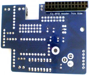
12. Solder the GPIO connector to the Bottom of the board

Make sure you solder this to the correct side of the board!

prc15 prc14


13. Fit the heatsink to the regulator

You will need to push the heatsink onto the regulator then adjust its position so the holes in PCB, regulator and heatsink line up. I find that poking a small screwdriver through the holes allows me to move around the components until the line up correctly. Then push the M3 nut inside the heatsink and screw in the M3 screw from teh bottom of the board

prc16


14. Attach the 12 Blue jumpers

These are used for various selections: ultrasonic pin, motor voltage input, motor enables (2) and level shifter selection (8)

prc17


15. Attach the Mounting spacer and fix to your Raspberry Pi (Rev B only)

To give a robust mounting of the PiRoCon onto the Raspberry Pi, we provide a metal spacing pillar 10mm and a 1mm thick washer. The spacing between the Pi and the board should be 11mm with this type of GPIO header, so both the metal spacer and the nylon washer should be used as shown below. If there is already a screw holding the Raspberry Pi to a case or similar, then you can remove the nylon washer to give the correct spacing for it to rest on top of the existing screw head

prc18prc19


16. Download code from our GitHub

  • MotorTestB.sb Allows control of the motors using arrow keys (ScratchGPIO)
  • PanTiltTest.sb Allows moving the pan/tilt assembly using arrow keys (ScratchGPIO)
  • UltraSonicTest.sb Shows operation of the UltraSonic sensor (ScartchGPIO)
  • TrackerTest.sb Uses the ultrasonic sensor on a Pan/Tilt assembly to follow (ScratchGPIO)
  • Avoider.sb Uses IR obstacle sensors and motors to avoid objects (ScratchGPIO)
  • InitioTest.sb Uses line sensors, obstacles sensors and motors (ScartchGPIO)
  • motors.py Python program to show motor operation

>> Wiring & Usage


#FreePiStuff – Sensor Shield

#FreePiStuff No.1

Pi-Sense 0.3 Prototype Kit

** THIS OFFER IS NOW CLOSED ***

What is it?

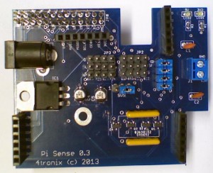
This a proto-type version of the upcoming 4tronix PiRoCon robotic controller board – which will be very different from this board (this one doesn’t include motor drivers for a start). This was the first design committed to a PCB, so a few mods are on the board but they do the job intended very well. Would seem a shame to let them go to waste, so I’d like them to be used.

This prototype kit features:

  1. 5V regulated power supply for the Pi, the board itself and any attached peripherals
  2. All 8 un-allocated GPIO pins brought out to 3-way headers with power, ground & signal
  3. 4 of these GPIO include bidirectional, 5V-3V3 level-shifters
  4. Level-shifters can be removed, or allocated to different pins by removing jumpers and replacing with jumper wire
  5. SPI female header for the SPI pins
  6. I2C/UART header for the obvious!
  7. Red LED for 5V, Yellow LED for 3V3
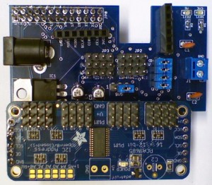
  8. Connectors to allow plugging on the Adafruit 16-Channel Servo/PWM Driver using PCA9685 chip (as shown in the photo above.

PCA9685-Fitted

What do I get for Free?

You will receive a prototype PCB with some mods on. All the surface mount components are ready-fitted, together with the 8, 3-way header pins (as the mods are on the back of these).

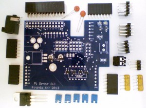
Loose components included for you to solder and complete the kit are:

  • 26-pin GPIO header
  • 2 x 100nF capacitors
  • 2 x 10K resistor networks
  • DC Jack socket
  • L4940V5 regulator
  • 8-pin female header
  • 3 x 6-pin female headers
  • 4×2 male header block
  • 3×1 male header
  • 2-pin screw terminal
  • 5 x 0.1” jumpers
  • Metal hex spacer and screws to mount the board to the Pi (not shown)

Full-Pack


What don’t I get for Free?

You won’t get:

  • Any guarantee
  • Postage outside UK (£3.90 for standard airmail, £10.02 for registered)
  • DC Plug to plug into the jack socket
  • Adafruit PCA9685 board – see www.ebay.co.uk/itm/161107058694


OK Sounds Good – How do I build it?

There’s no particular order, and whichever order you choose, you will end up wishing that a certain component wasn’t there when you are adding another. This is my preferred order:

  1. Solder the small orange 100nF capacitors C1 and C2. It doesn’t matter which way round
  2. Solder the 2 yellow resistor networks. You need to get these in the right holes and the right way round
    1. For the correct holes, see the photo
    2. The writing needs to be to the top of the board (nearest the 4×3 connectors)
    3. Insert the 6-way and 8-way female headers, turn the board upside down to rest on the headers to keep them straight, then solder 1-pin only on each header
    4. Check that the headers are sitting straight. Adjust if necessary, then solder the rest of the pins
    5. Add in the 4x2and the 3×1 male header blocks. Again solder one pin on each, check it is sitting straight, then solder the remaining pins
    6. Solder the 2-pin connector if required
    7. Solder the L4940V regulator. Do this by putting it in vertically as far is it fits easily and solder it in this position. When soldered, simply bend it backwards into the position shown in the photo. Make sure the Red modification wire is still attached to the pin underneath
    8. Fit the DC Jack socket – big holes so lots of solder to keep it nice and sturdy
    9. Fit the GPIO socket. I know it’s obvious but fit this on the opposite side of the board to everything else!

Complete


How do I test it?

Carefully! We don’t want a blown Pi. I have been doing the following:

  1. Give it a careful check for solder shorts, stray bits of wire, etc
  2. Don’t connect the jumpers at this point
  3. Plug a battery pack (6.5V – 10V) into the DC jack socket and check the 5V LED comes on
  4. Remove the battery pack
  5. Plug the board, without external power, onto a Pi and power up the Pi (no need for an SD card at this stage), and check that both the 5V and 3V3 LEDs light up
  6. Check you have the correct voltages on the middle pins of the two 4×3 header blocks (3V3 on the left block and 5V on the right block)


How do I use it?

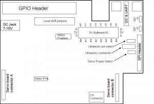
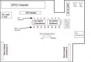
Use the rough sketch below to identify the locations of all headers. Due to the slight unexpected feature (bug), the silk screen is wrong for the 3-pin headers. The sketch below is correct:

  • Pins on the GPIO socket numbered 11, 12, 13, 14 are brought directly on the header
  • Pins 7, 22, 16, 18 are passed through 4 jumpers (level shift selectors) and then through the bidirectional level shifters . Leave all 4 jumpers in place if you want these 4 signals to be level shifted. Remove any jumper that you don’t want level shifting and you can use the exposed male header pin to access that signal, or use the opposite pin to feed any other signal through the level shifters. Is that clear? No, I thought not.
  • On the SPI header, the 8th pin marked 5V on silk screen is not connected
  • If you add in the PCA9685 board, you should build it with 2 male headers on the bottom of the board. Then it can be plugged directly into the female headers provided
  • The “Servo power select” jumper allows you to select the power for the servos on the PCA9685 board. Vin is the direct power from the 2-pin screw terminal. “Battery” is actually the 5V line which is common for the Pi and the board. This is fine to use for small servos or perhaps 1 or 2 larger servos if the batteries are in use. Use the external screw terminal power if more or larger servos are in use
  • Demos of board in use with a customer here: http://youtu.be/SKDD_sO2Rs4 and http://youtu.be/TS5DAGg9MJ4

pisen03_02

Click to enlarge


How do I Get one then?

Well, first off, there’s only 5 available. We’ll allocate on a first come, first served basis.

Send an email with #FreePiStuff in the title, including your name and postal address, to sales@4tronix.co.uk