ZBot80 – Robot for RC2014 Mini

For Christmas 2019 I received the gift of a RC2014 Mini kit and I/O Board. This is a Z80 board that runs micro BASIC (other languages and operating systems are available). This was a great gift, because the first computer I ever designed used a Z80 CPU, so it took me back to my youth. See the RC2014 website for details and to purchase some of their excellent products.
Obviously, 4tronix is now known for developing small robots for various micro-controllers (Microbit, Raspberry Pi, Arduino, etc) so I clearly had to design a robot for this exciting new (old) computer.
The easiest way for me to do this would be to put an ATMega328P and a motor controller on a board and write a little firmware to handle commands from the Z80. But that goes against the spirit of the whole RC2014 ethos, so of course I had to design it using mainly 74 series logic gates. This post describes the specification and the design.
Specification
- 4 x N20 Micro Metal Gear Motors. 6V, 240 rpm
- Motor Driver chip: L293D
- 2 channels of bi-directional PWM output. One channel for both left-side motors and the other channel for both right-side motors
- Each PWM channel can take values from 0 to 127
- Value 0 is motor off completely (0 %)
- Value 127 is actually motor on for 127/128 of the time (99.22 %)
- Z80 data writes are 8 bits. The bottom 7 bits define the PWM value (0 to 127). The top bit decides whether the motor turns forwards or backwards.
- There are two 8-bit storage registers to hold the PWM and Direction bits for each channel.
- The 2 registers then feed into the PWM generators (one for each channel)
- The outputs of the PWM generators drive the L293D motor controller.
- In addition to the logic there is a battery holder for 2 x 18650 batteries and a (linear) 5V regulator to power the robot and the RC2014 Mini
Operation Description
Download the complete schematic from here
Input Registers
<Click any image to enlarge>
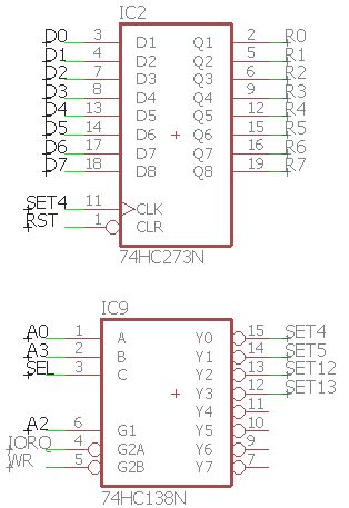
There are two ‘273 registers which are each 8-bit, one for each channel (Only one register shown above). We use the reset signal on the Z80 bus to reset them to zero when the Z80 is reset. This stops the motors turning randomly on startup. Pressing the reset button on the RC2014 will guarantee stopping the motors
The rest of the logic is to correctly assign addresses 4 and 5 to these 2 registers. The ‘138 takes addresses A0, A2 and A3 as inputs, together with the Z80’s I/O request (IORQ) and Write Request (WR) signals. If everything is valid then the data on the Z80 data bus is written to the selected register. In Micro Basic, use OUT 4,nn or OUT 5,nn to write the selected PWM values.
There is another enable signal fed into the ‘138, which isn’t shown here, called SEL. This is generated by 4 diodes connected to address lines A4, A5, A6 and A7 with a pull down resistor. This is simply further address decoding, allowing the higher value address to be used for something else in the future.
How Does PWM Work?
PWM stands for Pulse Width Modulation. DC Motors tend to work best at, or close to, their rated voltage. Simply turning the voltage down will reduce their speed but it will also considerably reduce the torque and it won’t be long before the motor stops altogether.
A far better way to control the speed is to switch the power to the motor from full power to zero power many times per second. If the motor power is on for half the time, then we say this is a PWM of 50%. If the motor power is on all the time then it is 100%. If it is never on then it is 0%.
[Note that this value does not give you the speed. A PWM value of 80% will not give you a speed of 80% of the full power speed. In fact it is likely to be much more than that.]
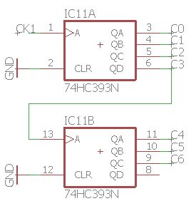
In this case, I am using 7 bits of each input register to determine the PWM value. So I also have a ‘393 binary counter that continually counts from 0 to 127. The ‘393 is actually two separate 4-bit counters so we link the C3 output from the first into the clock of the second, creating a ripple counter. C7 is not needed as we only need values from 0 to 127
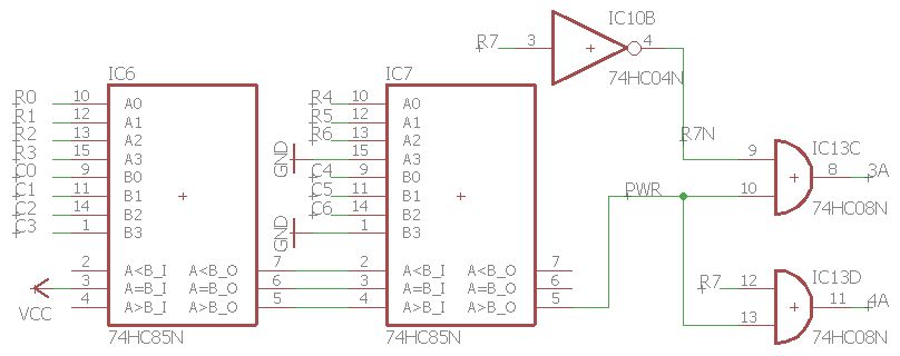
We then use a pair of ’85 comparator chips (2 chips per channel) to see if the counter value is less than the value in the register. If it is, then the appropriate input signal to the motor driver chip is enabled. The top bit of each register determines whether we drive the “Forwards” or “Reverse” signals on the motor driver
The other thing we need to consider is the frequency of the PWM signal. For these motors I usually find that a frequency of 30Hz to 100Hz is appropriate. I am using a very simple oscillator circuit made from two inverters, a capacitor and a resistor.
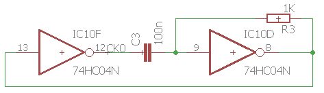
I set the capacitor to 100nF (as I had some around!) and the resistor to 1K. This gave a clock frequency of 5kHz. As were are counting in units of 128, the output frequency as seen by the motors will be 5000/128 = 39Hz. A bit low, but quite usable. It would probably be better to use 10nF capacitor and 4K7 resistor.
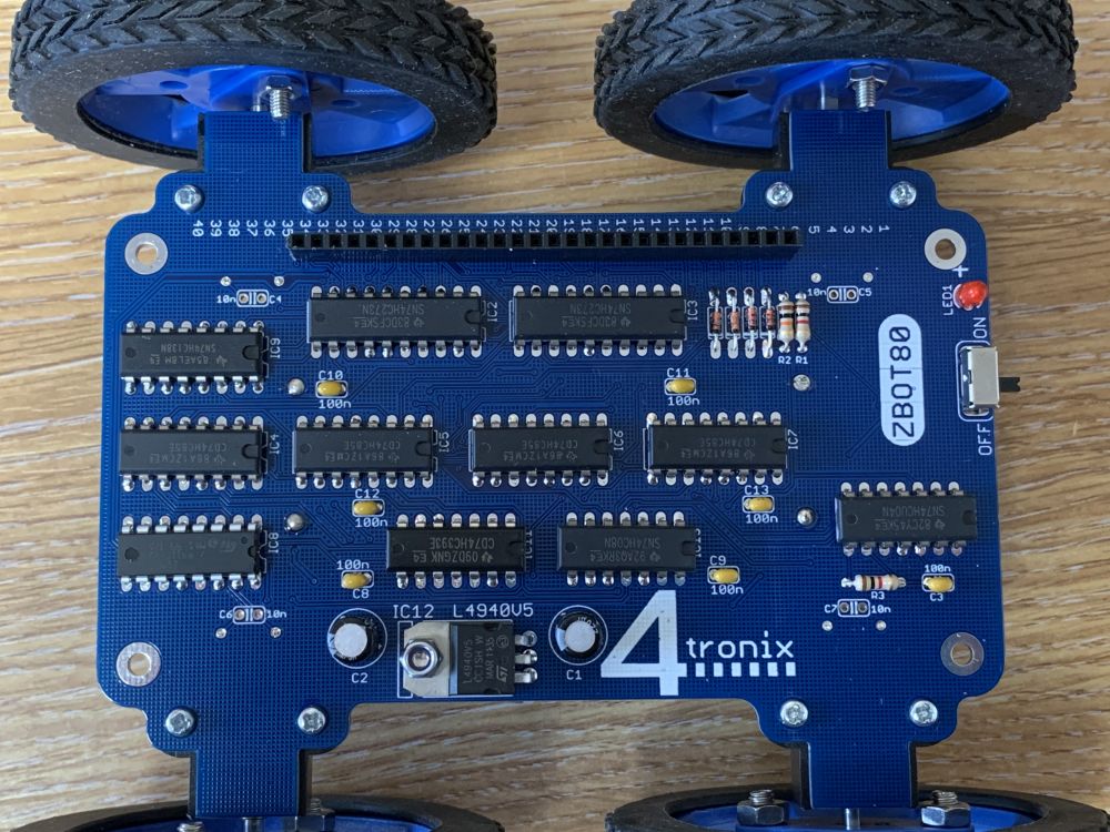
Completed Board
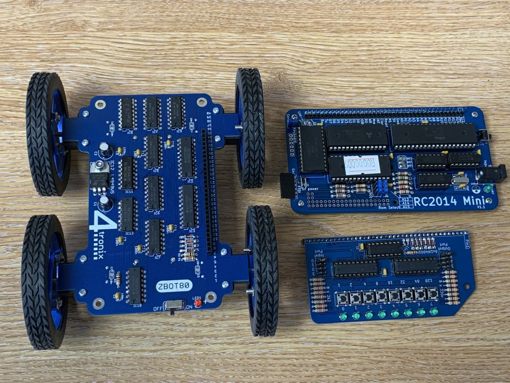
To fit this to the RC2014 Mini, you need to have downward facing male pins on the Z80 bus on the RC2014 Mini. As I also fitted the RC2014 I/O board to allow me to control the robot, I also needed upward facing pins. The answer was to fit to the RC2014 Mini a header with long pins. First I moved the plastic that holds the pins together so that it was central (push the small end into a female header, then pin-by-pin push each pin into the female header as far as it will go).

This gave me male pins on both sides of the RC2014 Mini so I could then fit both the ZBot80 and the I/O Board onto it:


Programming
To move the ZBot80 forwards, set both channels to the same speed forwards. Eg. Forwards at speed 60:
OUT 4,60
OUT 5,60
To move backwards, set both channels to the same speed, remembering to add 128 to each value (ie. set the top bit). So Reverse at 60 is:
OUT 4,188
OUT 5,188
To spin the ZBot80, set opposite speeds to each side. eg:
OUT 4,60
OUT 5,188
The rest is “just software” as my old boss used to say…