Really Useless Box
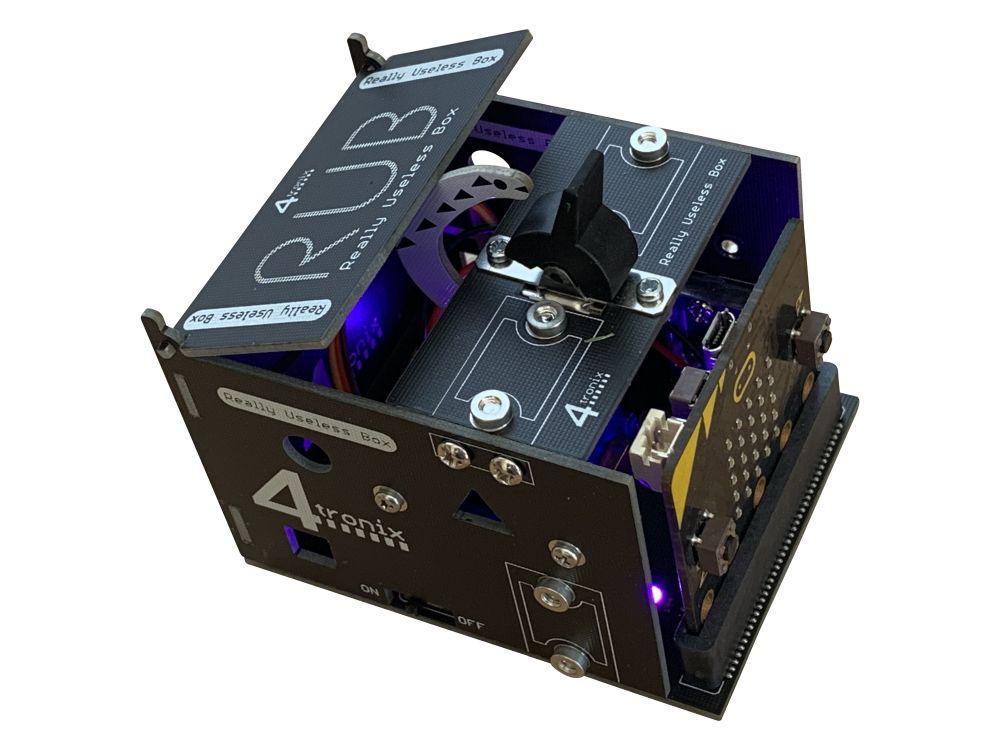
The concept of a “Really Useless Box”, where the human moves a switch and then the box closes it again, has been around for years. This is the 4tronix take on it, adding Microbit control of the servo (position and speed of movement) as well as Fireleds to give it more ambience.
There is an accompanying Makecode extension to make it even easier to code. This extension could easily be used for your own version of a Really Useless Box: simply connect your switch to Pin 0 and your servo to Pin 1 and you can use it. If you also have some Fireleds (or neopixels) then you can connect these to Pin 2.
Purchase
You can purchase the 4tronix Really Useless Box here, or feel free to build your own and use the Makecode extension.
Assembly
Click on any image to enlarge
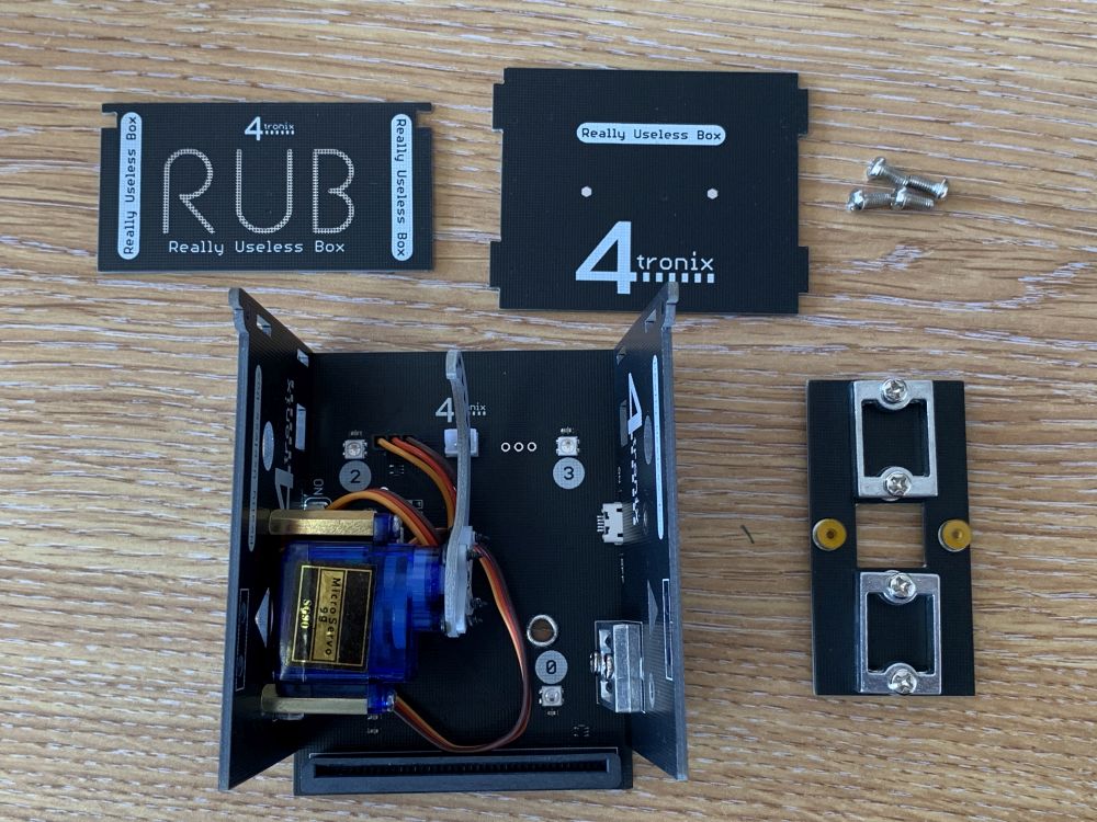
Step 1: Check you have the Correct Parts

You should have:
- 7 PCBs (6 black, 1 white)
- Main PCB with all components (base)
- Left side
- Right side
- End
- Top
- Lid
- Actuator (White)
- Bag with servo and fixings
- Bag with pre-wired Switch
- Bag with aluminium brackets and 8 fixing screws (M3, 8mm)
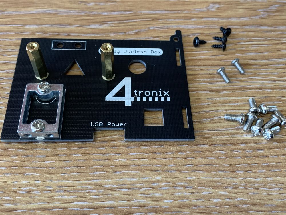
- Bag with an assortment of screws and rubber feet
- 2 x M2, 4mm screws (to fit switch)
- 2 x M2.5, 6mm screws (to fit servo and pillars)
- 2 x M2.5, 18mm female-female brass pillars (to mount servo)
- 4 x Black self-tapping screws (to mount servo arm to the actuator PCB)
- 8 x M3, 6mm screws (to fit PCBs to aluminium brackets)
- 4 x rubber feet
- Screw driver (reversible – unplug blade from handle and turn round for flat blade)
Step 2: Fit the Aluminium Brackets

There are 4 brackets to fit. One on each Side and 2 on the Top.
Ensure that the two threaded holes in the top of each bracket are at the edge of the PCB. Failure to do this will prevent you fitting the Sides/Top
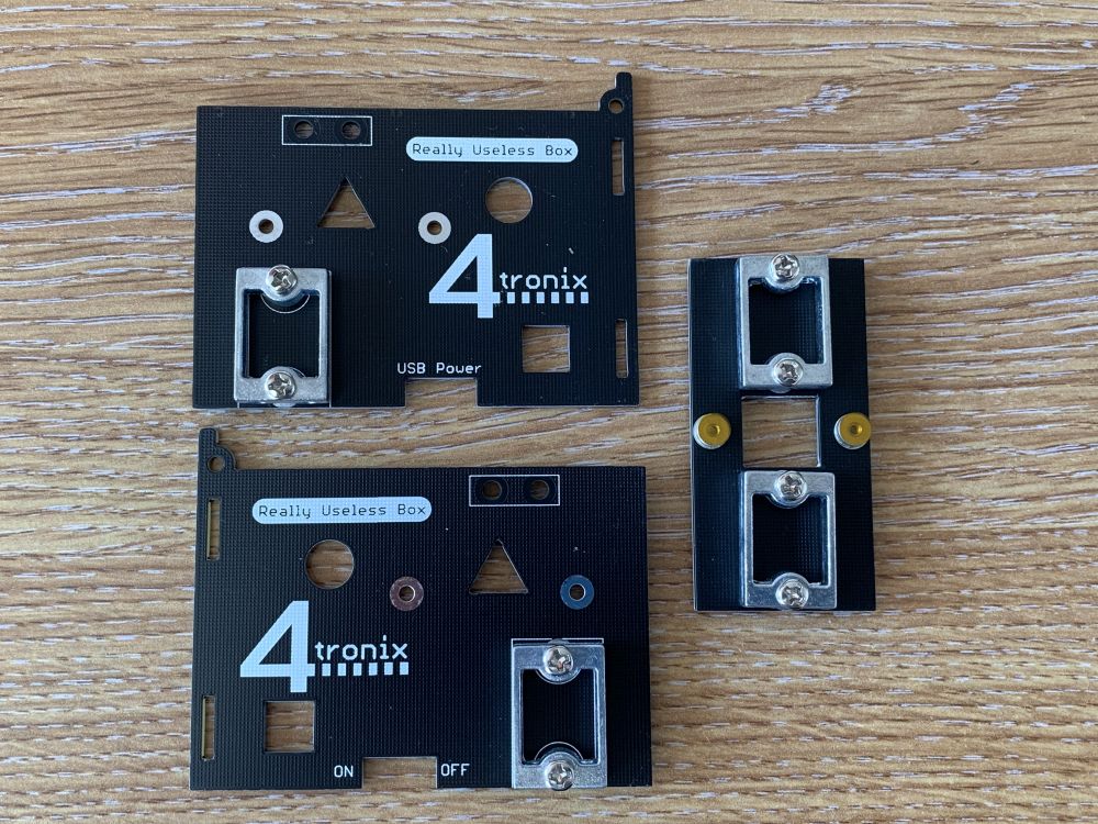
When complete it should look like the above photo.
Step 3: Fit the Servo to Left Side

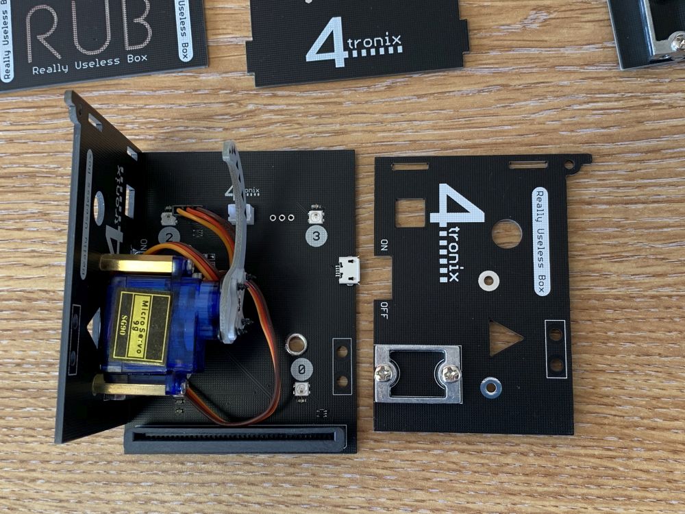
Screw the 2 brass pillars to the Left Side using 2 of the four M2.5, 6mm screws, ensuring that the pillars are on the same side as the aluminium bracket.
Finally, screw the servo on to the top of the pillars using the remaining 2 of the M2.5, 6mm screws. Ensure the cable from the servo is towards the centre of the PCB as shown below.

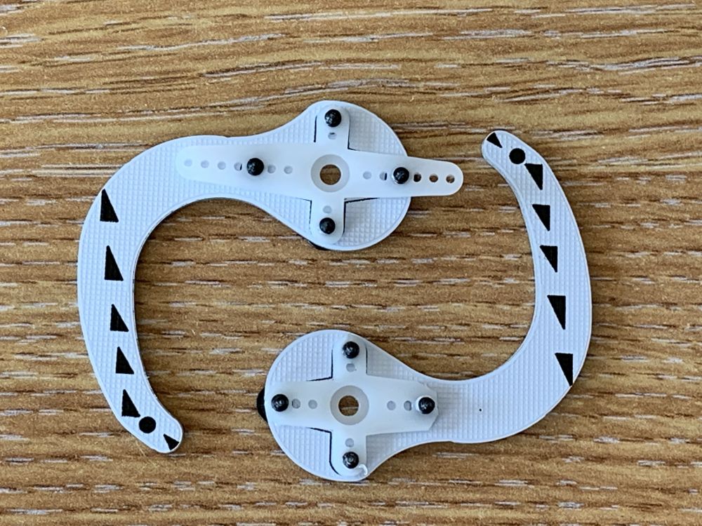
Step 4: Fit the Servo Arm to the Actuator PCB

Take the cross shaped Servo Arm from the Servo bag and push it through the hole in the Actuator PCB. It may be a tight fit.
Make sure you push it in from the side shown above, which has the markings for the arm on the Actuator.
Then use the 4 black screws to fix the Servo Arm from the opposite side.

Finally, use a pair of side-cutters or nail-clippers to trim the Servo Arm to size
Step 5: Fit the Actuator to the Servo

THIS IS CRUCIAL – DO NOT SKIP THIS
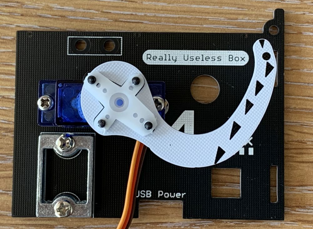
We need to set the servo into the correct place and then position the actuator so that the tip is just below the flat top of the side – as shown above.
To do this we need to connect the servo to the main PCB, plug in a Microbit and power, and write a very small program.
- Plug the servo into the Main PCB 3-pin connector. Ensure that the Brown wire is closest to the centre of the board, as shown above.
- Plug your Microbit into the socket, ensuring that the LEDs on the Microbit face away from the main PCB
- Connect your Microbit to your computer with a USB cable
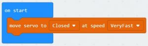
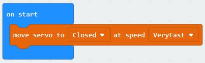
- Load the Servo setup program from here onto your computer. It should have a single line in the “on start” block
- Click on “Edit”, then click on “Download” to install it on your
- Move the USB cable from the Microbit to the RUB Main PCB and switch ON. The Servo should now move to the “Closed” position
- Now push on the Actuator so that the tip of it is just below the top edge of the Side PCB as shown below:
Unplug the Microbit and USB cable.
Finally use the very small screw in the Servo bag of fixings to fix the Actuator in position.
Step 6: Screw The Box Loosely Together

First the Left Side PCB. Use 2 of the eight M3, 6mm screws fitted from underneath the main PCB and into the 2 screw holes in the aluminium bracket on the Left Side. Leave the screws loose so the side can move a little.
Repeat for the Right Side PCB
Now use the remaining 4 M3, 6mm screws to fit the top piece to the side pieces. Again, leave the screws loose at this stage.

Take the switch and pass the wires through the square hole in the Top PCB.
NB. Ensure that the Red wire is nearest the centre of the box, as shown below
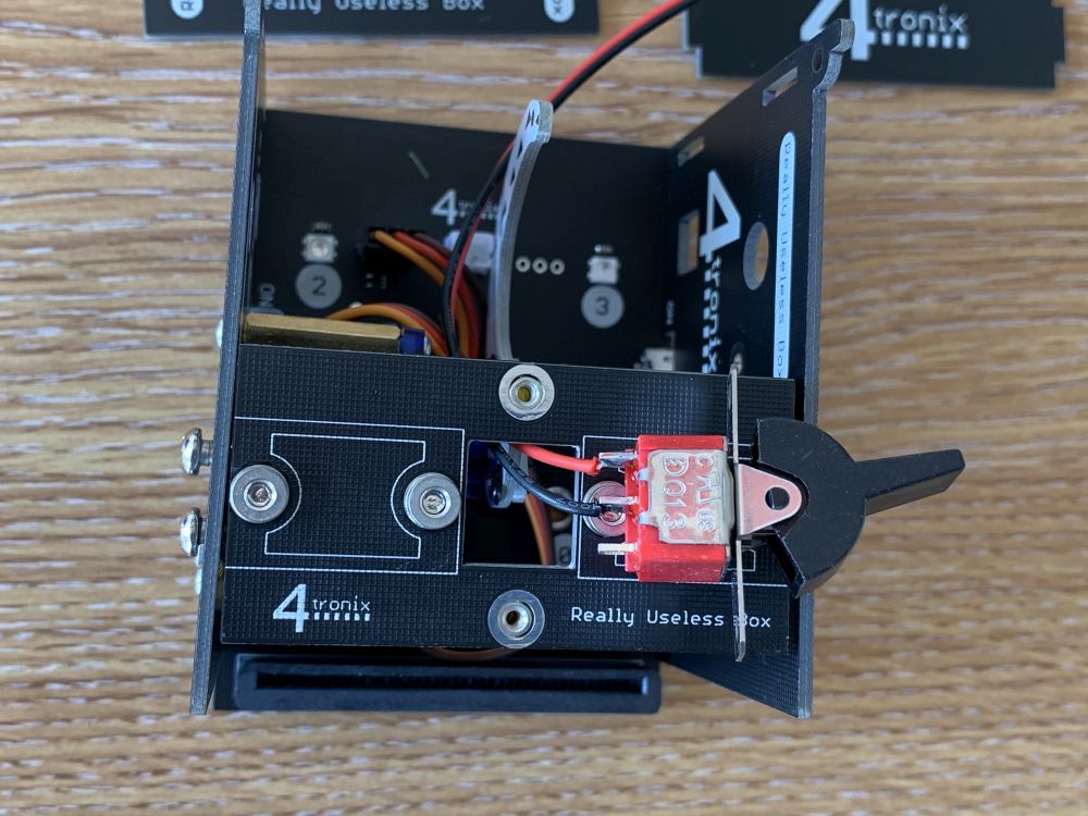
Use the 2 M2, 4mm screws to fit the switch tightly into the top
NOTE: If you fix the switch the wrong way round it will interfere with the servo, so make sure you have it fixed correctly
Finally, plug the end of the switch cable into the white JST socket on the mainboard
Step 7: Finish Assembly

Now, clip the End PCB into the slots on the back edge of the Sides, then push the small lugs on the sides of the Lid into the holes at the top of the Sides.
Then you can tighten all the screws to hold it all together firmly
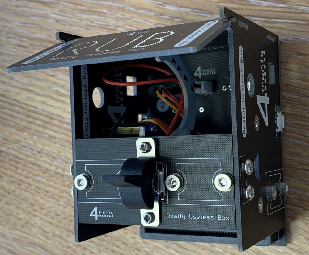
Move the lid up and down a few times to loosen it and remove any burrs. It should drop under its own weight, but can be a bit stiff until used a couple of times.
Finally, peel the 4 rubber feet off the backing and stick them in the corners of the base so it sits on a desk without sliding around and scratching the desk.
Programming the Really Useless Box
In some ways, the RUB is very simple to program – after all, it is only a switch, a servo and some LEDs. However, you can make it come alive and show its own personality. You can make it slight open the boix to have a look round, then go back in to hide. Or maybe it can come straight out in a rush as soon as you flick the switch. The best Really Useless Boxes exhibit a variety of behaviours at random so you never know what will happen when you flick the switch. Have fun designing your behaviours!
NOTE: The servo will not have sufficient power to move the switch unless you power the RUB from the USB connector on the side. Don’t forget to do this.
To start with you can run this simple test program from this link. This will set the LEDs to Red, then change to Green when the switch is activated and will switch itself off (and back to Red)
To program it yourself, first load up Microsoft Makecode from this link and select “New Project”.
Then go to Advanced, then Extensions. Insert the following URL into the search box and press Enter: https://github.com/4tronix/RUB
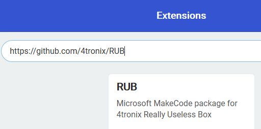
After selecting the extension you will see a Rub category in the Makecode toolbox. Clicking on that will show subcategories for Switch, Servo, Fireleds and more.

Switch subCategory
This subcategory has 2 blocks. The most useful one is the “On Switch On/Off” block which enables you to run code only when the switch is moved to a new position.
The other block allows you to check what state the switch is in (On or Off) at any time, using the standard Logic blocks.
Servo subCategory
This subcategory has a number of blocks that enable you to move the servo directly to any position, or to make it move at a selected speed from “Very Slow” to “Very Fast”. In fact, “Very Fast” is the same as moving the servo directly – the Servo moves at its fastest pace.
As well as moving to a specified angle, there are 3 preset positons of the Servo labelled Closed. Open and Switched. You can use the “set closed open switched” block to set the positions of these presets in degrees. If you have built the RUB as described above then you should find the default positions are okay.
NOTE: The servo is limited in software to only travel between the Closed and the Switched positions. So setting these presets, also sets the servo maximum travel
You will find that, if the Servo is moving very slowly then it may need to go an extra distance to get enough power to open the switch. In this case, either move to a higher number of degree or set the switched position to be higher.
You can use the block “wait for servo” to hold up running the program until the servo has reached the position you set. This is important otherwise your program might start moving the servo again before it has had a chance to get where you told it to.
NB. The very first servo command in the program will ALWAYS go at full speed irrespective of what speed was set. This is because the software needs to know where the servo is before it can start controlling it slowly. The first time it is used, the software doesn’t know where it is so it moves directly to a known position.
Fireled and more subCategories
This is the standard set of commands for driving Fireleds. You can set all the Fireleds at once, or set them individually. The default is automatic updates, so the Fireleds are updated automatically after every change (with only 4 Fireleds, it is probably not worth changing this)