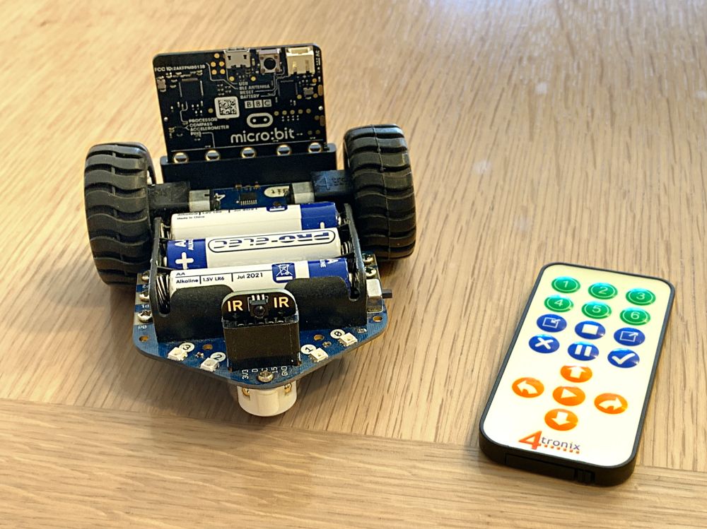
The 4tronix infrared keypad and receiver works with MiniBit, BitBot XL and Robobit Mk3 robots. Simply plug the IR Receiver dongle into the front interface port of the robot, with the sensor pointing forwards. Then remove the clear plastic battery tab from the keypad and you’re ready to go. Here is one fitted in a MiniBit.
Programming
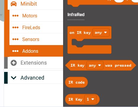
You can find the InfraRed blocks in the Makecode extension for your robot, in the category “Addons”.
The IR receiver is very easy to use in your program. You can set up as many different event blocks as you need; one for every key on the keypad if you want. Each event block will be run when the selected key on keypad is pressed. You can also have an event block that is triggered by any of the keys being pressed, then decide in the block what to do based on the specific key that was pressed. This is useful in some scenarios.
Note that the keys on the keypad are labelled with numbers and symbols, but you can use them to do whatever you need. There is no specific mapping between the keys on the keypad and what you do with that information in your program. You could use the “up arrow” key to spin 90 degrees left if you want.
Note also that there is no pairing between the infrared keypad and the receiver in the robot. Any receiver that “sees” the message from the keypad can respond to it. This is great if you want multiple robots to start dancing at the same time for instance. On the other hand, in a classroom environment you probably don’t want all the robots to be controlled from a single keypad. It isn’t really that bad though, because the keypads are fairly directional and the range isn’t very far, so you could point the keypad at a particular robot and reasonably expect only that one to respond.
There are 4 Makecode Blocks for the InfraRed, as shown below
This is an example of a single key triggering an event block:
Here we have selected the “Up arrow” and when that is pressed, a Rainbow display is shown on the Fireleds and the robot moves foward 30cm
In this example we trigger the block on any key being pressed, then check inside the block to see which key was actually pressed:
We select the “any” key and then use if..then blocks to run the options. This allows us to do something that is common to all the functions in just the one place – in this case, “set LED rainbow”. You can also use the “if key was pressed” blocks within a loop to exit – for instance, in one of the line following loops to stop it moving.
The latest incarnation of the hugely popular BitBot is the new BitBot PRO, with on-board processor providing intelligent and accurate motor control, with sensor resolution of over 100 pulses per centimetre. Driving straight has never been so easy.
We’ve also taken the opportunity to upgrade and improve many other features; including the sounder, the line follower sensors and even the power supply circuit – as well as adding several extra mounting holes for you to fix your DIY updates. Finally, there is an infraRed receiver to enable simple remote control using the 4tronix InfraRed remote controller (optional extra) – note that the remote control is not paired to any particular BitBot PRO, so all nearby units in line of sight will receive the same commands.
Of course, we have also updated the Makecode Extension to support all the new features:
New blocks for accurate movements of the wheels; motion in a straight line by a selected distance, spinning a determined angle and even moving in an arc of a user-define radius and angle. You can also read back the distance and angle moved.
New blocks for both Digital and Analog line sensors, as well as enabling user or automatic adjustment of threshhold values. Finally a merge of all the line sensors to give a single value estimating where the line is, from -100 for on the far left, through 0 in the centre to +100 on the far right.
New blocks for the sounder to support changing volume, pitch and duration. Note also that the sounder can now use the Makecode Music blocks as well
New blocks for the InfraRed receiver: event driven blocks that are run when specific keys are pressed, as well as being able to test the last key pressed
Motor Control
The new motors used in BitBot PRO are small metal-geared motors with a nominal speed of 155 rpm at 6V and a gear ratio of 100. On the back of the motor is a black magnetic disk which provides about 100 pulses per revolution of the wheel. The onboard software uses these pulses to work out how far each wheel has travelled and when to speed up or slow down and stop so that the correct number of pulses has been counted when the command has finished. This allows for much more accurate straight line movement as well as accurate distances and angles.
The existing (pre BitBot PRO) commands for the motors still work and, in most instances, they now allow for “straight line” driving automatically using the PID control loop (see below). It is important and useful to note that the “move … motor … ” block shown below does not use the straight line control and will drive motors using the normal method.
In the “Motors” section of the new Makecode Extension for BitBot PRO, there are several commands for selecting a specific movement. These are mostly self explanatory. Here are a few examples
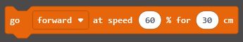
This command allows you to select the direction (forwards or reverse), the speed (0 to 100) and the distance to travel in centimetres
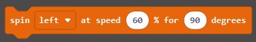
This command lets you spin on the spot to the left or right, at a selected speed (0 to 100) and for any number of degrees.
Then you can combine these two commands in a loop and very simply draw an accurate square.
In fact, just by changing a couple of the numbers you can draw any regular shape. This one is a hexagon. We’ve changed the number of iterations of the loop to 6 (number of sides we want) and the angle turned each time to 60 degrees (360 divided by number of sides)
Moving in an arc is managed by the BitBot PRO calculating the required speed of each motor and the distance each motor has to travel to move the number of degrees required at the radius set. If you do an arc of 360 degrees, you will have drawn a full circle.
PID Control
The control software for the motors is called a PID Control Loop. The PID acronym stands for Proportional, Integral, Derivative and refers to the three elements that define how far each motor is from the correct speed, distance and acceleration. This function can be turned off and then you get the standard motor control you have used in the past. It is very important that you do turn off the PID control if you are doing a lot of rapid changes to the motor speeds – such as for some line following programs or reacting to distance sensor changes. The PID control only works if it is given time to speed up and slow down.
The PID control loop is a complex algorithm that essentially does three things:
Tries to keep both motors going at the selected speed – starting slowly and accelerating to reach the selected speed (soft start)
Tries to keep both motors going at the same average speed so that the distance covered by both motors is the same
Stops the motors when they have reached the selected distance
Because the speed ramps up to the selected value, starting the command repeatedly will keep resetting the speed back to the starting value. This potentially means that the motor will never actually start moving (depending on battery levels, friction, etc)
Even if you give it enough time to get moving between starting new commands you may find that the overall path is not straight. This is because there hasn’t been enough time to stabilise both motors
Because of these two issues, we strongly recommend switching off the PID control if you are repeatedly setting new movement commands.
These should be printed clearly on a laser printer. We use these track elements as our test tracks, so we are confident these will work well.
There are several improvements added to the BitBot PRO beyond earlier versions of BitBot. We have added an extra, central, sensor and all the sensors are now Analog although we have provided both Digital and Analog Makecode blocks. We have also added a block that merges all line sensor blocks into a single “line position” number from -100 for far left, to +100 for far right. Now we can code several methods/algorithms for line following programs:
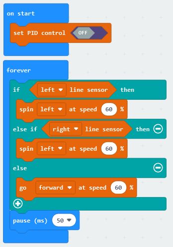
Classic Digital Sensor Line following:
This method simply drives forward if no line sensor is active, or spins left/right if the associated sensor is active. You may need to adjust the speeds and pause values for the best results. It typically results in a successful, but rather jerky, movement.
Classic Analog Sensor Line Following:
This method sets the speed of each motor to be proportional to the related sensor. The line sensor can have values from 0 (perfectly non reflective) to 1023 (perfectly reflective), but the motors require values from 0 to 100. Therefore we need to adjust the values – the numbers shown may not be the best that you can achieve, so you should check the values you actually receive on your line following mat/drawing/printout and scale the numbers accordingly so that the white area gives 100 and the black area gives 0. It results in a very smooth line follower.
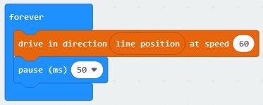
New “Merged Value” Line Following:
The new, merged value, “line position” block can be directly combined with the new “drive in direction…” block to produce an extremely simple and smoothly operating line follower program. The “drive in direction…” block requires a direction from -100 for turn left, through 0 for go straight, to +100 for turn right. These are the same values that the “line position” block produces. As this is all done “behind the scenes” it doesn’t necessarily produce the most reliable or fastest line follower. As with all of these line follower examples, if you go too fast then you will drop off the line.
InfraRed Receiver
The BitBot PRO has an integrated infrared receiver at the front, next to the accessory connector. However, the Infrared remote control handset is not included to save cost as not all customers will want it. It is available as an optional extra.
The IR receiver is very easy to use in your program. You can set up as many different event blocks as you need; one for every key on the keypad if you want. Each event block will be run when the selected key on keypad is pressed. You can also have an event block that is triggered by any of the keys being pressed, then decide in the block what to do based on the specific key that was pressed. This is useful in some scenarios.
Note that the keys on the keypad are labelled with numbers and symbols, but you can use them to do whatever you need. There is no specific mapping between the keys on the keypad and what you do with that information in your program. You could use the “up arrow” key to spin 90 degrees left if you want.
Note also that there is no pairing between the infrared keypad and the BitBot PRO. Any BitBot PRO that “sees” the message from the keypad can respond to it. This is great if you want multiple BitBot PROs to start dancing at the same time for instance. On the other hand, in a classroom environment you probably don’t want all the BitBot PROs to be controlled from a single keypad. It isn’t really that bad though, because the keypads are fairly directional and the range isn’t very far, so you could point the keypad at a particular BitBot PRO and reasonably expect only that one to respond.
This is an example of a single key triggering an event block:
Here we have selected the “Up arrow” and when that is pressed, a Rainbow display is shown on the Fireleds and the BitBot PRO moves forward 30cm
In this example we trigger the block on any key being pressed, then check inside the block to see which key was actually pressed:
We select the “any” key and then use if..then blocks to run the options. This allows us to do something that is common to all the functions in just the one place – in this case, “set led rainbow”. You can also use the “if key was pressed” blocks within a loop to exit – for instance, in one of the line following loops to stop it moving.
Starts BitBot PRO moving forward or reverse at a speed from 0 to 100% of full speed. It will travel the distance specified and then stop. Both the distance and the speed can be negative, so going forward at -60% speed will actually move in reverse. Note that full speed is less than on BitBot XL for two reasons: 1) The motors are more highly geared, and 2) the PID control algorithm requires some “head room” to ensure both motors can go at the same speed
Starts the BitBot PRO spinning on the spot left (anti-clockwise) or right (clockwise). The speed can be from 0 to 100% of full speed. Both the speed and the number of degrees can be negative, so spinning left at -60% speed will spin right, for example
Calculates the different speeds required for each motor, based on the radius and the nominal speed. Keeps moving until a stop or other motor command is issued
Calculates the different speeds required for each motor, based on the radius and the nominal speed. Stops after the selected number of degrees has been turned. The angle turned can be negative as well as positive
This block does not use the PID control. The direction can vary from -100 to +100. It drives each wheel individually so the BitBot PRO turns sharp left when the direction is -100, goes straight when direction is 0 and turns sharp right when the direction is +100. For intermediate directions, it will curve to the side at a shallow or steep curve depending on the direction. This block can be used on its own, but it is mainly expected to be used with the “line position” block to implement a simple line follower
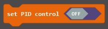
If your program is rapidly changing the speeds or directions of motors, such as in a line following program, you don’t want the PID control software to keep trying to control the motors. Use this block to switch off the PID control, or switch it back on again
This block returns the distance moved by the selected wheel (or the average of the two) since the last reset of the sensor count. You can see the result as millimeters, centimeters, inches or pulses. Moving forwards will increase the count and reversing will reduce the count. This counts at the same rate as the system counter used in the PID control, but is not the same counter because resets will occur at different times
This block gives the angle turned in degrees since the last reset of the sensor counts, based on the difference between the left and right wheel counts
This block will reset to zero the counters used in the distance and angle turned blocks above
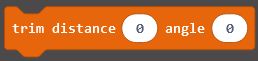
This block should rarely be used and when used must be used carefully. Because of manufacturing tolerances on the wheel diameter and wheel spacing, it may be that the BitBot PRO does not move or turn exactly the correct distance. This block allows you to make small adjustments to the default constants used internally to calculate movement distances and angles. Setting both the distance and angle trims to 0 will return the constants to the factory default values. Setting them positive will make the BitBot PRO travel further or turn a larger angle. Setting them negative will shorten the distance or reduce the angle. Both trims can have values from -100 to +100 and the maximum values will change the distance by about 20%. See the trouble shooting section for more details.
EEROM
This block allows you to store a byte value into the user area of the EEROM. The bytes are addressed from 0 to 200. This data is stored permanently in the BitBot PRO, even if the power is switched off or the batteries removed. You could, for instance, use it to store a sequence of moves that are checked in your program when it starts to determine where the BitBot PRO will move
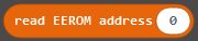
This block reads the value stored in the address specified in the user area of the EEROM. The value is a byte which is interpreted as -128 to + 127. The address can be from 0 to 200
Line sensors
This block provides the analog value (0 to 1023) of the selected line sensor. There are three line sensors on the BitBot PRO, which are sensitive to infrared reflected off the surface below. A totally non-reflective surface (in complete darkness) would give a value of 0, whereas an extremely bright source of infrared would give a value of 1023. Typical values for a laser printed line on photocopier paper are about 180 for the white paper and 70 for the black line – but these values can vary greatly. Also be aware that any source of infrared light (eg. sunlight through windows or torches) can cause the reading on the sensors to be higher
This block returns “True” if the selected sensor recognises a black line, otherwise it returns “False”. It can be used directly in an If..then..else block. The internal software checks the analog value from the sensor against a threshold and a hysteresis value (guard band) to determine if the value is a black line or not. You can set these values if required using the next two blocks
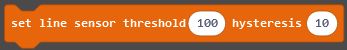
This block sets the threshold and hysteresis (guard band) values for all the line sensors to the values given. The factory default settings are 100 and 10 as shown above. These values are stored in the system area of the EEROM so will be valid even after switching off and removing batteries etc
This is another block to allow setting the threshold and hysteresis values for the line sensors. In this case it causes the BitBot PRO to enter a special routine that will sense the reflective and non-reflective surface below, then set the threhold and hysteresis values separately for each sensor. The process is as follows:
Sets the front two FireLeds on each arm to Red
Waits until it detects a reflective (eg. White) surface below on all sensors, then sets the front two FireLeds on each arm to Orange
Then move the BitBot PRO by hand over and off a black line five times, making sure all wheels and the front caster stay on the surface so the distance to the sensors is constant.
As you move the sensors over and off the line you will see the indicator LEDs for each sensor go on and off.
When it has done this five times on all the sensors the front FireLeds are set to Green for 2 seconds
Finally, the front 2 FireLeds on each arm are set back to their original colours and the process is ended. The new data is saved in the system EEROM
Power
This block gives the battery voltage on the BitBot PRO in volts. Note that the value will be lower if the motors are moving or the FireLeds are on bright. Also note that alkaline batteries will give a higher voltage than rechargeable batteries. So ensure that you compare under similar conditions if using this to determine whether the batteries need changing or not
InfraRed
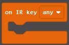
Use this event block to run some specific code when the selected key is pressed on the InfraRed remote control keypad. You can have as many of these event blocks in your program as you like, as long as they all use different IR keys. You can also select the “any” key as shown above. This event will run when any of the keys on the keypad are pressed. However, when any other IR events will run as well is a lottery as it depends on the order they are checked, so it is best to not use any other IR events if you use the “any” key
In some situations you may not want to run a separate block of code when an InfraRed key is pressed, but you still want to know if a certain key has been pressed – maybe if you want to stop doing something if the “stop” button is pressed. Then you can use and if..then block to check a specific (or any) key is pressed and act accordingly
This block just returns the key code of the last IR key pressed. You could then compare it with a specific key (from the block below, for instance) or a particular value
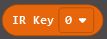
This block gives the key code of the selected key. You can use it to compare against the last IR code pressed (see the block above) to see if that key was pressed
Trouble Shooting
As we are trying to produce, across thousands of units, accurate distances and angles essentially via dead-reckoning, it is likely that manufacturing tolerances will creep in and cause inaccuracies in movement. Don’t worry, this can be easily resolved.
Inaccurate Distance
The distance moved is determined by the diameter of the wheels and the number of pulses on the sensors. The diameter can be different from the nominal value due to manufacturing tolerances. In addition, the wheels may slip on the surface being used, or there could be a build up of dirt on the wheels.
You can correct for any deviation by setting the distance “trim” appropriately. Note that a trim of 0 is the factory default value.
If you ask the BitBot PRO to move 30cm and measure the distance to be higher than this, then set the trim to a negative value. Alternatively, if it actually moves a bit less than the desired distance, then set the trim to a positive value. Once you have set this value, you shouldn’t have to do it again because the trim value is stored permanently in the EEROM on the BitBot PRO.
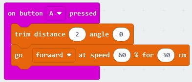
In the test below we have found that setting the distance trim to 2 gives an accurate distance travelled. Now we can move on to making the angle turned more accurate.
Inaccurate Angle
The angle turned is very sensitive to the actual distance between the wheels. It also depends on an accurate distance measurement, so you should always trim the distance value, before setting the trim for angles.
Mechanical Fix
The wheels used on the BitBot PRO have an outer stop so that they can’t be pushed on too far. However, the actual distance between the wheels can vary because of several mechanical factors. If the BitBot PRO turns too far, then you need the wheels further apart. If the BitBot PRO doesn’t quite turn far enough, then push the wheels together a little.
Software Fix
It is far better to fix any deviation in turn angle by using the trim angle block as we did for the distance. But first, ensure the wheels are pushed together as far as they go against the end stop.
Put a marker on the floor in front of the BitBot PRO, then ask the BitBot PRO to spin 360 degrees and check if it is still pointing at the marker. Change the trim angle and repeat the test until you are happy. You will need to increase the trim angle if it doesn’t turn far enough, or reduce the trim angle if it turns too far.
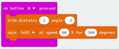
In this example (leaving the distance trim at 2 from the previous test), we have found that a negative value of -1 is all that is required to get a very accurate turn over 360 degrees.
Once the trimming has been done, you don’t need to use the trim block again and you can use the BitBot PRO as normal, but it will be more accurate as it will remember these trim values.
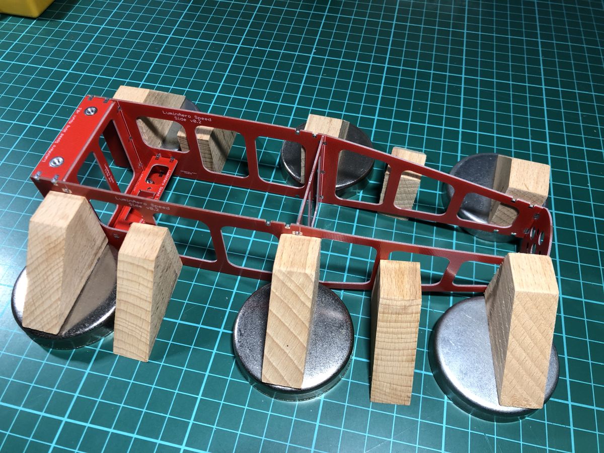
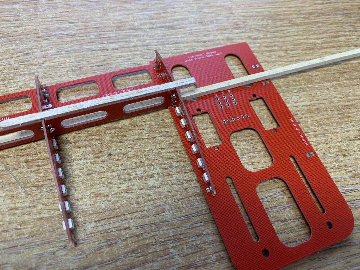
I suggest that you place the two sides vertically on your building board, place F1 and two of the F2 in place then hold it together with elastic bands. You don’t want to squeeze it too tight. Then fit the wing and hatch mounts and the servo mount.
Place a bit of weight over the top to hold everything flat to the table, and check everything is square.
Once you’re happy, quickly solder one or two pads on each PCB join, so it holds itself together. Note that just tacking single joints like this makes each joint very weak, so don’t put any twist or pressure on it.
Check again that everything is straight and true, then solder everything else. There’s a lot of solder joints to do. Top and bottom, inside and outside, etc.
You should now have a solid monocoque.
You can download plans in PDF format for the fuselage sides. These can be printed full size on multiple A4 sheets, or just use the dimensions given to cut them out – all edges are straight lines so it’s easy.
Cut the two sides out, following the plan and ensure they are identical. Then line them up one at a time against the PCB assembly. When you’re sure it’s in the correct place, press the balsa against the PCB joins to mark where to remove bits of balsa. This will allow the balsa sheet to fit directly against the PCB.
[Photos required]
Use epoxy and spread it over the PCB where the balsa contacts, then attach both sides and clip them against PCBs. I use lots of small bulldog clips for this.
Click to enlarge
Wing
The wing is much more fiddly than the fuselage as the pieces are smaller and there’s a lot of them.
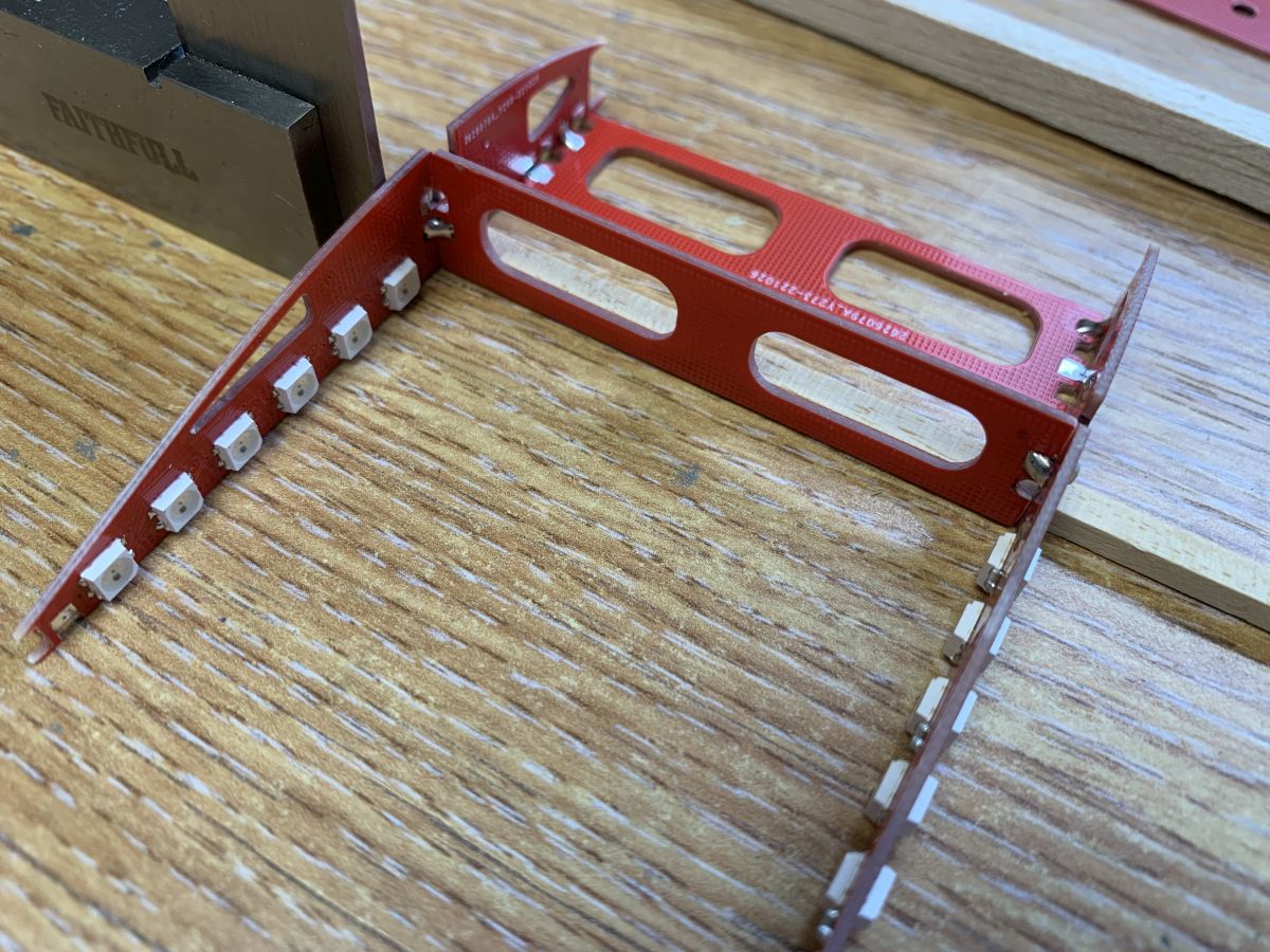
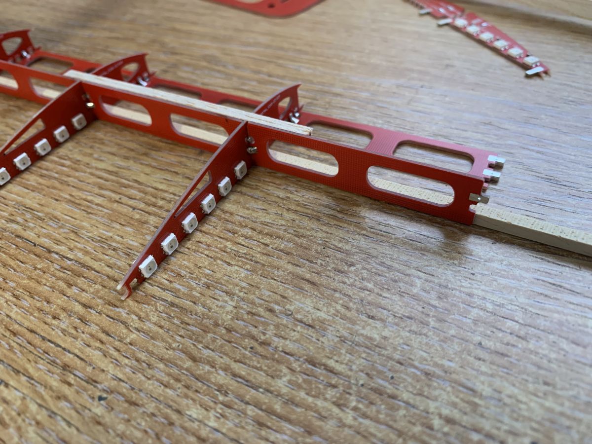
I find it easiest to start from one side and work my way across to the middle, then back out to the other side. The images below show working from Port to Starboard.
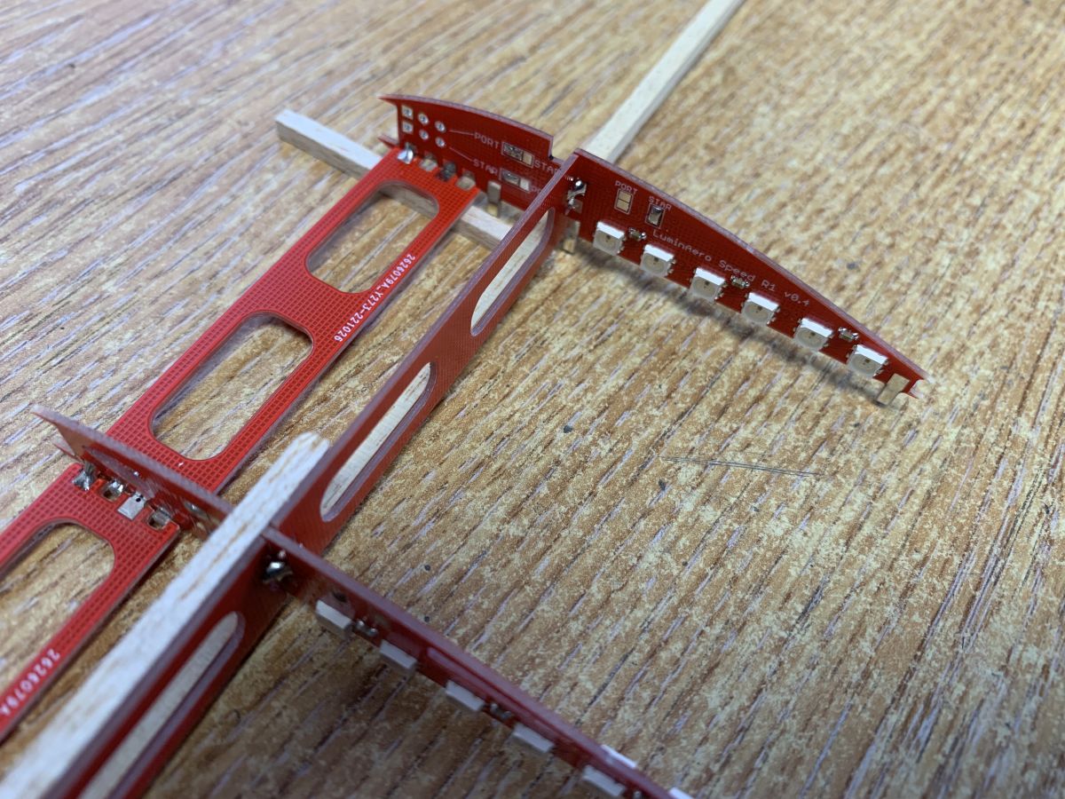
1 Check the parts are correct
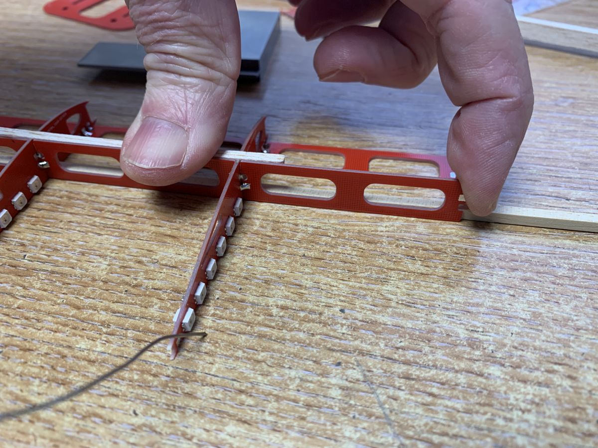
Port set on left from wingtip at bottom to root rib at top. Starboard on right from wingtip at top to root rib at bottom. Note the different configuration jumper settings on each rib and the tabs on the root ribsPlace Root Rib over the lower spar and use a small square to ensure rib is vertical and at right angles to the spar. Note the orientation of the horizontal brace – production code visible and at the rearSolder one joint to the root rib on each of horizontal and vertical braces Then solder one joint of each onto the first main rib Use finger pressure and soldering iron to melt solder and ensure both braces are fully against each rib to ensure they are squareHere you can see the vertical brace with the inboard side tab at the top and the outboard tab at the bottom. This is crucial !Start adding the horizontal and vertical brace for the next panel Again ensure that both ends are fully against the ribsUse a small piece of 1/8″ square balsa to help line up the top of the vertical bracesHere you can see the braces being pushed against the rib to ensure tightness. At the same time, use a soldering iron in the other hand to melt the solder jointsSqueezing the two horizontal braces either side of a rib. Use soldering iron to melt the two solder joints while the pressure is being appliedUse a bit of scrap balsa to lift up the braces near the root rib because of the tabs on the bottom of it Take particular care to ensure this rib is square in all directionsSolder the root rib to the base, ensuring it is fully pressed down front and rear Note the orientation of the base, with the components underneath
Continue adding ribs, starting with the Starboard root rib, all the way to the wing tip.
Ensure that the higher tab on the vertical web braces is on the inboard side – this means the PCBs are the opposite way around from the port wing.
Check that everything is totally square and flat to the building board – you will need a gap in the building board, or use two boards, to enable the centre section to lie below the level of the rest of the wing.
When everything is square, solder up all the joints. Remember that every joint (except those on the edges of PCBs) has four solder positions: top, bottom, left, right.
1.1.4 Fixed bug with negative temoperature readings
1.1.3 Fixed bug with Absolute mode setting incorrect values
1.1.2 Initial “Working” Release
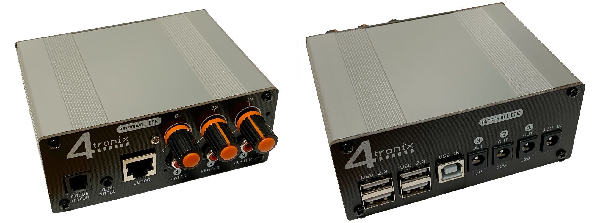
Product Overview
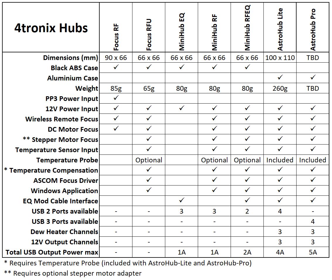
There are a number of products in the range that can be controlled and/or monitored using the AStroHub application software.
Each product comprises a selection of standard building blocks, so you can select the one in the range that has the appropriate set of blocks for your equipment.
These building blocks are:
USB hub with various quantity, power output and type of USB connections
Focus motor control. DC motors and stepper motors
Temperature monitoring with optional temperature probe and focus temperature compensation
EQMod direct connection for many SkyWatcher (and Orion) mounts
Focuser Motor Control
The same focus motor control is used for all products, except the Focus RF (which doesn’t have a connection to the application).
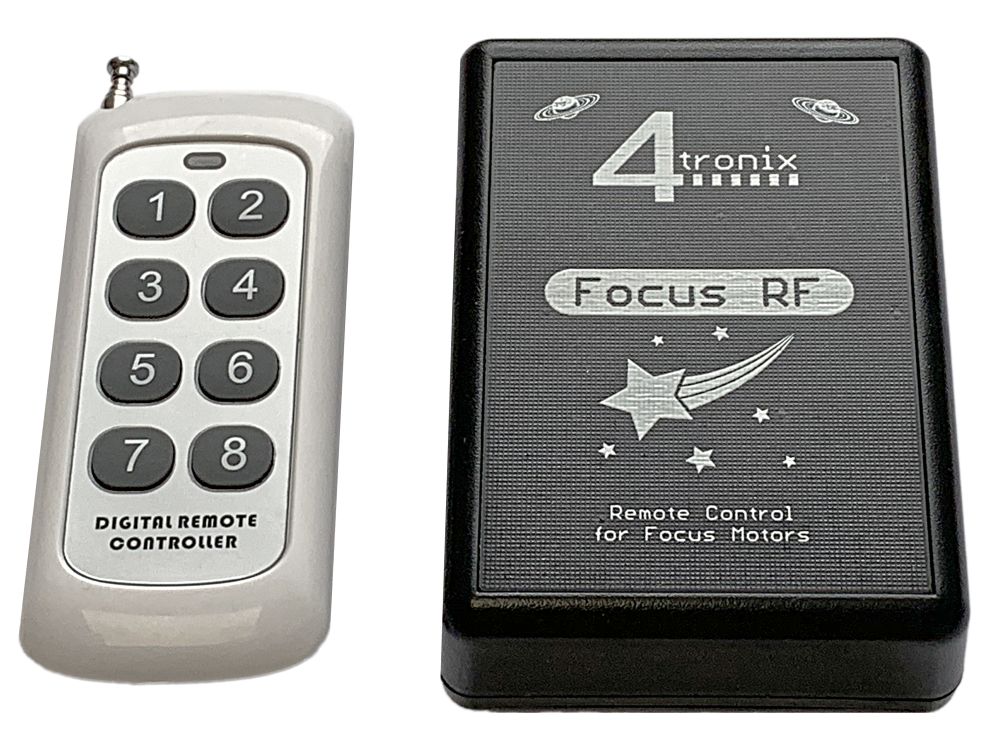
Remote Controller
For Focus RF, the remote controller uses buttons 1, 3, 5 and 7 to move the motor one way; and buttons 2, 4, 6 and 8 to move it the other way. Buttons 1 and 2 are the slowest and buttons 7 and 8 are full speed. You can set the slowest speed so that it works on your rig. See the Focus RF blog for more details.
For Focus RFU, MiniHubs and AstroHubs the remote has two different modes of operation:
Continuous. If Button 7 is pressed then continuous mode is selected. Here the buttons 1 to 6 work in the same was as for Focus RF – while the button is held pressed the motor will continue to run (*). Buttons 1, 2 are slowest and buttons 5,6 are fastest. The speeds can be set using the Windows app
Step mode. If button 8 is pressed then stepping mode is selected. Pressing buttons 1 or 2 will move one “stride”, pressing 3 or 4 will move 5 “strides” and pressing 5 or 6 will move 25 “strides”. Each “stride” can be set to a number of steps from 1 upwards, by using the Windows app. This step mode allows changes via the remote control to be fed back to the Windows app, or ASCOM driver so that the absolute or relative position of the focuser is reported.
(*) Continuous movement of the motor will stop if a command is sent to the unit over USB. The USB commands will take precedence over the remote controller. You can set the scan rate if using the Windows app so it doesn’t interrupt too often.
Selecting DC or Stepper Motors
All except Focus RF can support stepper motors (both Unipolar and Bipolar) as well as DC motors. Everything is configured for DC motors when shipped, so you will need to change this using the Windows app if you want to use stepper motors.
There are two parts to operating stepper motors. Firstly, you need to wire up the motor correctly either by making a cable, or by using the optional focus motor adapter. Secondly, you need to set the stepper motor characteristics in the software – either via the ASCOM setup dialog, or from the Windows app, depending which you are using.
Wiring Motors
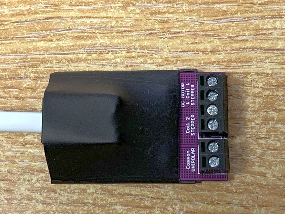
In this section we will use the Focus Motor Adapter PCB as shown below. You will need an RJ22 cable to connect from the Focus RFU, MiniHub or AstroHub to the adapter.
DC Motors: Use the top two connections labelled “DC Motor & Coil 1”
Bipolar (4-wire) Stepper Motors: Use the top 2 connectors for coil 1 and the next 2 for coil 2
Unipolar (5-wire) Stepper Motors: Use the top 2 connectors for coil 1 and the next 2 for coil 2. Then use either of the bottom connectors for the common/power wire.
For all stepper motors, you may have to experiment with the polarity of each coil before it operates as expected. Every motor is different, but they all need their coils to be energised in the correct sequence and the correct polarity
Setting in Software
In the Windows app or the ASCOM driver setup dialog, you can select the type of motor you are using (DC, Bipolar or Unipolar).
For stepper motors you can also set the step delay in ms. This is the delay between each step of the sequence and again will vary from motor to motor. You should set it to a slow value (say 10 – 20 ms) to begin with until you are sure you have the wiring connected correctly. Then speed it up until the motor runs smoothly. Probably around 2 – 5 ms.
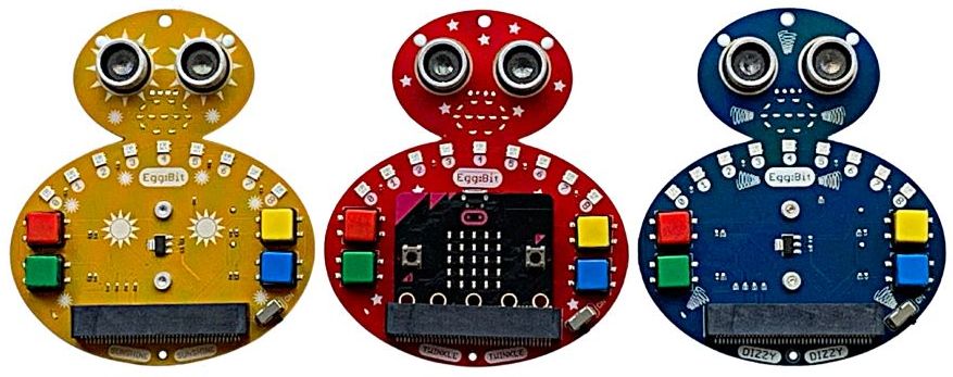
EggBit is a new wearable product for the popular Microbit. It comes with built-in RGB lights, buttons, animatable LED mouth and ultrasonic distance sensor. It also incoporates a battery pack, on/off switch, indicator LED and power circuitry.
EggBit is available in 3 functionally identical flavours: Sunshine, Twinkle and Dizzy
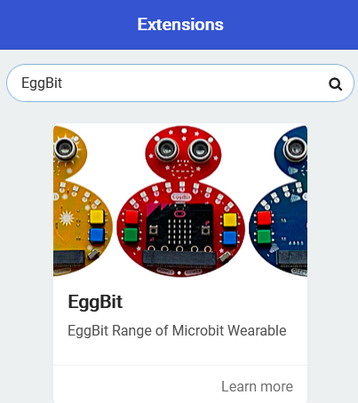
Coding them in Makecode is simpe. There is a Makecode extension written especially for them. Seacrh for EggBit in the EXtension search box.
Programming with Makecode
First you should load the EggBit extension to Makecode. Go to the Advanced section and select Extensions. Then in the search box, search for EggBit and then press Enter.
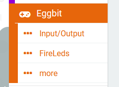
Then you can explore the various options. Within the EggBit extension are three categories: Input/Output, FireLeds and More
Input/Output section contains blocks to work with the buttons, the animatable mouth and the iultrasonic distance sensor.
FireLeds section contains the basic functions for driving the nine FireLeds, including use as a Larson scanner and a bar graph,
More section contains the advanced FireLed functions. Generally these will not be required.
Buttons
The four buttons can be coded in different ways. At any time in your code you can check the state of the button: whether it is pressed or not pressed. Alternatively, you can select a block that is only activated when the specified button is pressed or released (event-driven programming).
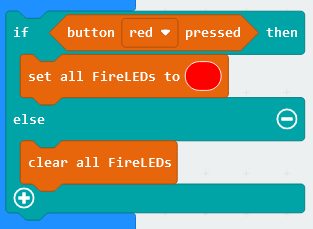
The following shows the method of checking the state of a button. This block is a “Boolean” value which can give the result True or False. It returns True if the button is currently pressed, otherwise it returns False. So it can be used directly in an if/then/else block as shown below. This example sets all the FireLeds to Red if the red button is pressed, otherwise it switches them off.
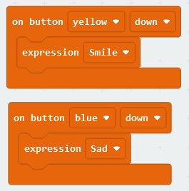
Using the event-driven model is equally simple. Select the button you want and whether you want to activate the block when the button is pressed, or when it is realeased. Then within the block you can run any code. The following two blocks set the mouth to Smile when the Yellow button is pressed and set it to Sad when the Blue button is pressed.
Mouth
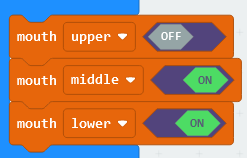
The animatable mouth has three separately controllable sections: Upper, Middle and Lower. You can control these sections individually if you like, or you can use the predefined expressions. As there are three sections and each can be either On or Off, there are eight possible configurations of the mouth.
For instance, to make an open, happy smile you would light the middle and lower sections, leaving the upper section off. You can do this by setting each part individually, like this:
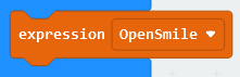
Or you could use the predefined expression, OpenSmile:
Ultrasonic Distance Sensor
This is a standard HC-SR04 type sensor that is specified to work from a few centimeters to a couple of metres. Note that as the beam angle is large, the further away the obstacle is, the larger it needs to be to provide sufficient reflection. This is normal behaviour.
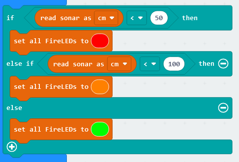
There is only one block for the ultrasonic sensor, which returns the distance to the nearest reflective object. You can select whether to get the answer in centimetres, inches or microseconds. In the following example, we set the FireLeds to Red if the object is less than 50cm away, Orange if less than 1m away, otherwise we set it to Green.
FireLeds
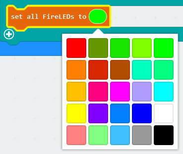
The EggBit has nine FireLeds, which are individually addressable RGB LEDs. You may have previously known them as neopixels. Each FireLed can be set to any of 16 million different colours, because the brightness of Red, Green and Blue components can each be set using 8 bit data (256 values each). To simplify setting the colours, we have produced a palette of 25 basic colours
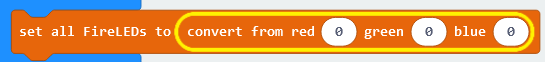
However, you can set the colour directly using the “convert from red, green, blue” block in the More category. Simply drop the convert block on top of the colour:
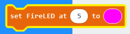
As well as setting all FireLeds to a specific colour, you can switch them all off using the “Clear all FireLeds” block, or set just a single FireLed to a specific colour using the “set FireLed at” block. The nine FireLeds on EggBit are clearly labelled with their number, from 0 to 8. This example sets FireLed 5 to Pink
Larson Scanner
You can set the Larson Scanner going by specifying the colour to use and the delay between display updates. The shorter the delay, the faster the scanner goes. Typically we set the colour as Red and the speed as 100 or 200ms
Use the “stop scanner” block to disable the scanner.
Bar Graph
The nine FireLeds can be configured as a bar graph, with the leftmost FireLed (0) being a low value and the rightmost (8) being a high value.
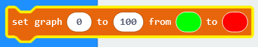
First, you must set up the parameters for the bar graph to work with. The system needs to know the colours to use for start and end and the value assoicated with the lowest LED and the highest LED. Use the “set graph” block to do this. The example below sets the range of values to be shown as 0 to 100 and the colours from Green to Red. The system will slowly change the colours so that the overall change starts at Green and ends at Red – in between there will be various shades of colour.
Now you can draw a bargraph by providing it with a number. The number doesn’t have to be in the range given, but anything higher than 100 (in the example above) woiuld be treated as 100, and anything lower than 0 would be treated as 0. The example below uses the value from the ultrasonic distance sensor to set the bargraph:
For the latest releases of Minibit and BitBot XL, 4tronix have added DriveStraight technology in the hardware and Makecode extensions.
This works using a Flash memory chip which stores the calibration details of the motors at three different speeds: 30%, 60% and 90%. This information is used to generate the actual speeds used for each motor to give the best chance of moving straight ahead when required.
Because this data is stored in permanent memory, it only needs to be calibrated once and then it will automatically be used from then on. You don’t have to do anything in your programs for it to be used and it doesn’t matter if you change the Microbit at any point. The calibration data is specific to the robot it is created on – it isn’t related to the Microbit at all. So you can swap between Microbits including v1 and v2 types.
You may find that the calibration data changes over time as the motors wear differently. If it gets too far out, then simply run the calibration program again.
DriveStraight is built into the latest Makecode extensions. It isn’t available in Python, although you can access the Flash memory from Python and use it yourself.
On the Minibit, you also have user access to the rest of the Flash memory. You can use this for what you like: storing sequences, remembering particular LED settings, etc. This feature will be added to the BitBot code shortly.
Note that this code only works on BitBot XL v1.2 or later, or Minibit v1.3 or later.
Process: The calibration program starts at speed 30 (displaying 3 on the Microbit LEDs). You then set the left or right speeds until it is driving straight. Then give the robot a good shake and it will change to speed 60 (displaying 6). Set this speed, shake again to change to speed 90 (displaying 9). Once this speed is set correctly, shake again and it will return to speed 30. You can then switch off and all the values are stored. If you run the program again, you will start from the un-calibrated values and must follow all the steps again.
Load the program into the Microbit and plug it into the robot
Switch on the robot. It will display 13 (indicating a v1.3 Minibit) or 5 (indicating a v1.2 BitBot XL), then change to show 3 (meaning speed 30)
Press A or B buttons to affect the turning left or right, then press both A+B simultaneously and the robot will display the current calibration value, then move forward for 2 seconds at speed 30.
If it is still not moving straight, press the appropriate button one or more times to straighten it up, then press A+B again to test it
When you’re happy that it is moving straight, give the robot a shake and it will store the values for speed 30 and move onto Speed 60.
Repeat for speed 60 and speed 90
When you’re happy that all three speeds are set correctly, then switch off. Don’t switch it back on again without changing the software in the Microbit, because the first action of the calibration program is to reset the calibration values.
The 4tronix dew heater controller is available in both 2-channel and 4-channel versions. Apart from the number of channels, they are identical in operation – in fact they use the same PCB and the same code on the internal microcontroller.
Each channel is fully variable from completely Off to permanently On. The positions in between are managed using PWM (Pulse Width Modulation), which is a method of reducing the overall power usage, while keeping the voltage level the same. Basically, it provides power at the input voltage for a certain percentage of the time, with the power off for the rest of the time during each period. Each PWM period is only about 2ms, so you won’t see any fluctuating values.
There is an indicator LED on each channel to give some indication of the power selected. If the indicator LED is Off, then there is no power being provided to the dew heater. If it is On solidly, then the full input voltage is being provided to the heater. In between, the LED flashes. A slow flash indicates little power and a fast flash (up to 30 Hz) indicates more power. Note that the flashing of the LED is not the same as the PWM values on the heater outputs.
The Dew Heater Controller can operate happily from about 7V up to about 15V. The driver for each channel is rated at over 4A, but do not use all 4 channels at 4A – other parts of the circuit won’t cope.
The power is supplied via a 5.5mm DC Jack, with centre Positive. There is a reverse polarity protection circuit inside, just in case you get it wrong.
Note: See the AstroHub blog page for information about the Focus RFU as the method of using the remote is different and for information on using the Windows application. There are more products available in our AstroHub and MiniHub ranges as shown here
Overview
The 4tronix Focus RF system replaces the manual handset in the Skywatcher compatible auto-focuser kit. It provides a simple wireless interface to control the motor at 4 different speeds with the fastest speed determined by the power supply used and the slowest speed being configurable.
The left buttons (1, 3, 5, 7) turn the motor one way and the right buttons (2, 4, 6, 8) turn the motor the other way. Buttons 1 and 2 are slowest, buttons 7 and 8 are fastest.
You can add, delete or replace remotes (requires the case to be opened)
Normal Operation
You can power the FocusRF from a 9V PP3 battery which can be fitted inside the case, or you can use an external 9V to 13V power supply with a 2.1mm DC Jack, centre positive.
Clip the end of the cable from the motor into the RJ22 in the FocusRF, instead of into the handset. All is now ready to go.
When the switch is moved to ON, the Red LED will initially come on solidly for a few seconds, then begin to flash slowly.
Press any of the buttons on the remote (which has already been paired to your FocusRF before shipping) and the green LED on the FocusRF will come on and go off again when you release the button. The focus motor will turn while you hold the button, then stop when you release it.
Speed Configuration
(Focus RF only) The default slowest speed may be too slow for your setup: the battery may not have the power to turn the motor, or the motor is too stiff to move for instance. Alternatively, you may want an even slower speed – especially if you are using an external power supply of more than 9V.
During the few seconds after switch on, when the Red LED is on solidly, press button 7, then 8 on the remote. This enters speed configuration mode.
Then press any of the buttons 1 to 8 to set the minimum speed. The default setting is 5. After pressing the selected speed, FocusRF will store the new minimum speed even during power down, removal of battery etc.
Pressing any button other than 7 then 8 at the start, will immediately move to normal operation and start moving the motor at the speed given.
Configuring RF Remotes
The 433MHz RF interface to the remote control is handled by a small daughter board inside the FocusRF unit. Using the button and the LED on the daughter board, you can add new remotes, delete all remotes and set configuration mode.
There are four screws on the bottom of the FocusRF case which you need to unscrew to get at the daughter board. You do not need to remove the internal PCB or the daughter board.
Add New Remote
Switch on the FocusRF
Press the button on the daughter board briefly – the Green LED on daughter board will light solidly
Press each button on the remote in turn, from 1 to 8. The Green LED will briefly turn off to acknowledge each button press.
When all 8 buttons have been pressed, press the button on the daughter board briefly again – the Green LED will turn off and the new remote is now stored
Delete All Remotes
For remotes since November 2021:
Switch on the Focus RF
Press the button on the daughter board three times in quick succession
The Green LED will flash quickly for a few seconds while it clears the memory
When the Green LED goes out, switch off the Focus RF
All stored remotes are now cleared
For remotes prior to November 2021: Note that this function also clears the configuration mode, so you will also have to reset this (next section)
Switch on the FocusRF
Press and hold the button on the daughter board
After a second or so, the Green LED will flash once (keep pressing the button)
The Green LED will then flash twice, then 3 times, 4 times, 5 times and 6 times
After it has flashed 6 times, release the button
The unit has now been reset and has forgotten all remotes and all configuration settings.
Set RF Configuration Mode
The RF module is capable of several operation modes. FocusRF uses Mode 1 or Mode 2 depending on the wireless receiver model that has been fitted. All other modes will result in unreliable operation. The following operation sets Mode 2, all units shipped after November 2021 use Mode 1 so stop after step 3 and release the button.
Switch on the FocusRF
Press and hold the button on the daughter board
After a second or so, the Green LED will flash once (keep pressing the button)
After another second, the Green LED will flash twice
When trying to get a planet such as Mars into the field of view at high magnification, you really need to see the cross-hairs in your finderscope. If you’ve been looking at a laptop for the last few minutes getting the settings right etc, you will have difficulty seeing the cross hairs. This nifty device shines 8 dim red LEDs onto the surface of the lens, making the cross hairs stand out clearly.
It doesn’t use a battery, just a super-capacitor. This means it can be charged very quickly in just one minute. The Start button turns the LEDs on for 45 seconds and then turns them off again to preserve the charge in the super capacitor. You can press the button at any time to get another 45 seconds worth of illumination. Typically one charge will last more than one session.
Finally, there is a small switch to adjust the brightness of the illumination from “Dim” to “Dimmer”.
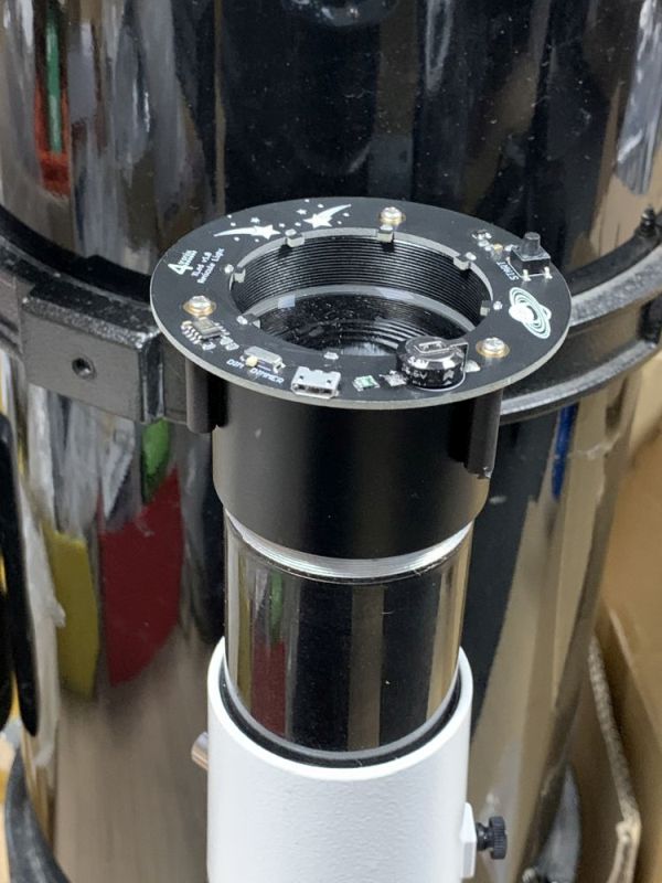
Fitting the XLed
This version is designed to fit snuggly around a 50mm finderscope such as those by SkyWatcher and Celestron.
The package contains 3 rubber coated pillars and 3 screws. Simply screw the pillars onto the bottom of the XLed. The pillars fit on the other side to the majority components and the pictures of Saturn, comet and stars.
Plug the XLed into a USB port and the LEDs will come on. Wait a minute (or until the LEDs turn off) and then you’re done.
Now slide the XLed onto the finderscope and press the button when you need illumination.
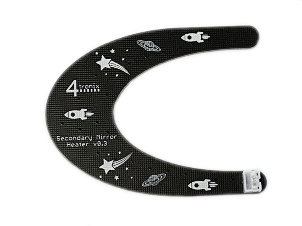
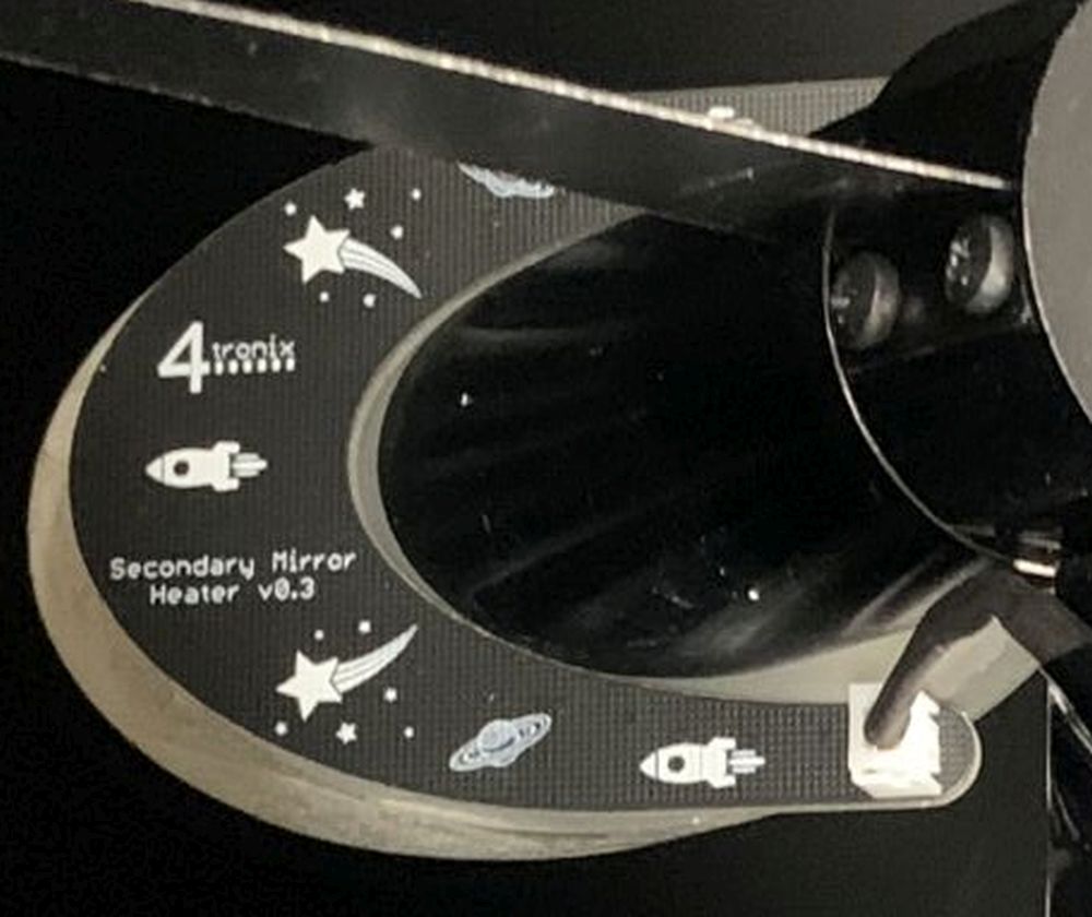
This heater panel is fitted to the rear of the secondary mirror in a Newtonian telescope (this model is designed for Skywatcher 200 or Celestron C8-N models).
A 12V supply, either direct or via a dew heater controller, is connected and then it will dissipate up to 3W over the rear surface of the mirror. This banishes dew and ice build up on the mirror’s surface.
The heater comprises 24 (varies with model) heater points (resistors) and so spreads the heat evenly across the surface. The heater panel is fixed using double-sided thermally conductive tape (included) or pre-fitted adhesive.
The connection to the panel itself is via a 2mm JST connector, but there is a JST to Phono cable included with thin wires to minimise damage to the light path.
Fitting Instructions
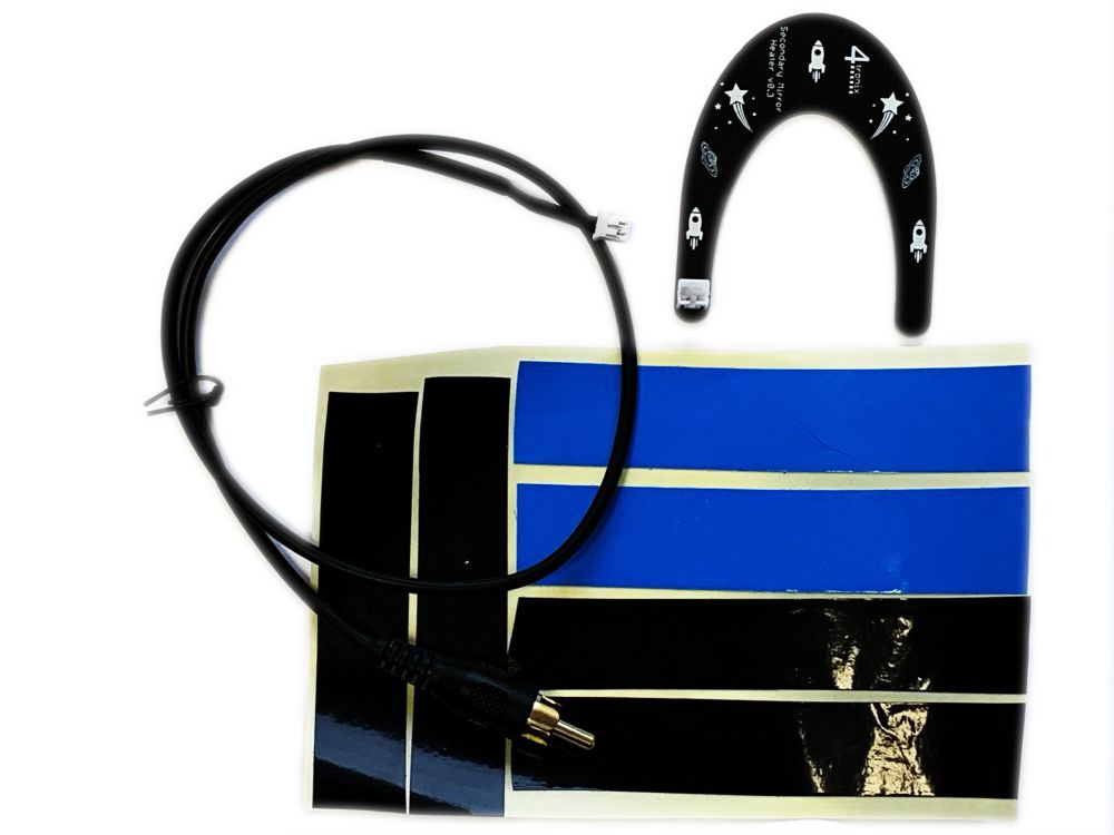
Step 1 – Check you have the Parts
You should have:
Heater PCBA
JST to Phono lead 50cm
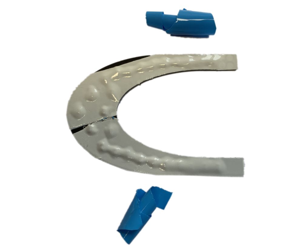
Sheet with pieces of Blue thermally conductive tape and black insulation tape (some models are supplied with pre-fitted adhesive instead of the blue tape)
Step 2 – Fit the Thermal Tape to the PCBA
Some models are supplied with pre-fitted adhesive. For these, you should peel off the backing paper carefully, then place the heater on the back of the mirror. You can move it for a while as long as it isn’t prssed on too hard, then the adhesive will set harder. Skip to step 3.
If you have the blue tapoe, then peel off the tape from the backing sheet and apply it to the side with the resistor chips on, making sure to cover all of the resistors. Cut the tapes where they cross, to ensure that there is NO overlap – we need the same height of adhesive all over so it attaches properly.
Then trim the excess tape away from the edges using a sharp craft knife or scissors, so it now looks as shown above.
Step 3 – Prepare to Fit to the Mirror
Peel the Blue backing tape off the double-sided tape as shown above.
You may find it easier to attach the Phono cable at this point. Pros: it’s easier to attach when the heater is not fixed to the mirror. Cons: it causes extra force on the heater while the adhesive is hardening (note that the adhesive never fully hardens, but it gets stronger after an hour or two – faster if the heater is switched on)
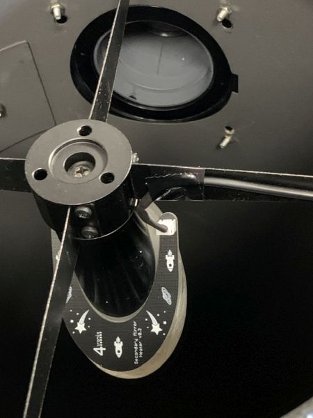
Step 4 – Attach the Heater to the Mirror
“Simply” press the heater PCBA onto the back of the mirror and leave it a while for the adhesive to cure. The adhesive does not harden fully, so you can always remove it in teh future if required.
The problem here is that a) you must not touch the front of the mirror with your fingers and b) you want to put as little force on the mirror mounting as possible. So use cotton gloves or a piece of tissue to protect the mirror and squeeze the PCB and mirror together – don’t push against the mirror, squeeze the two parts together.
Step 5 – Tape up the Phono Cable across the Mounting Vanes
Use the black tape provided to attach the cable to the mirror mounting vanes, doing your best to minimise the cable’s intrusion into the light path. You can run the cable along the top or the side of the vanes
Step 6 – Collimate your Telescope
With the best will in the world and taking great care, you are likely to have disturbed the position of the secondary mirror while fitting this accessory. You should collimate your telescope regularly anyway, so this shouldn’t be an issue. There are many online tutorials for collimation. I like this one:
Using Your Secondary Mirror Heater
This heater is designed to run off 12V DC. However, there is nothing specific about this voltage, so you could run at 5V or 20 V. At 5V it would give 500mW and at 20V it would give 8W – this is too much for your mirror. Unless the conditions are extreme, we recommend using at 12V, running at 50% on your PWM dew heater controller. If you don’t have one, then running at 12V is fine.
The 50cm cable provided is short, so that it can be left attached to the telescope at all times. To use it, you probably want an extension cable – these are available online from many places at reasonable prices and at different lengths. Search for “RCA extension cable”.