
Author: admin
CrumbleBot – Assembling, Coding, Extending
CrumbleBot Assembly and Usage

Download a PDF of this Article
Introduction
The CrumbleBot is a fantastic way to introduce coding with the Crumble to children of all ages, and especially primary school children. It provides a ready-built platform to experiment safely and easily with analog and digital, inputs and outputs. It moves, it shines lights and it reacts to its environment – but only if your coding tells it to.
In this guide we take you through the process of assembling the CrumbleBot and show you how to start coding to do real-world physical computing. Before you know it, the children will be telling you how to improve it!
See the end of this article for some program examples:
- Know your CrumbleBot
- Let’s Get Moving
- Let There be Light
- Follow that Line!
- Finding the Light
- Check that Switch!
- Obstacle Avoiding
Assembling CrumbleBot
Nothing could be simpler really, but let’s break it down into a few easy steps
First check out this video from Inspired Minds
Step 1 – Check you have all the Parts

You should have the following items in the CrumbleBot kit and you will also require a Crumble (of course!)
- Main CrumbleBot Circuit board (white, 100 x 80mm) with all components fitted, including 2 micro metal gear motors
- 2 black wheels
- Ready-assembled front caster with 2 screws
- 6 mounting pillars to fit the Crumble: 5mm, M2.5, Female-Female
- 12 small screws to fit the pillars: 4mm, M2.5, countersunk head
Step 2 – Fit the Wheels to the Motors
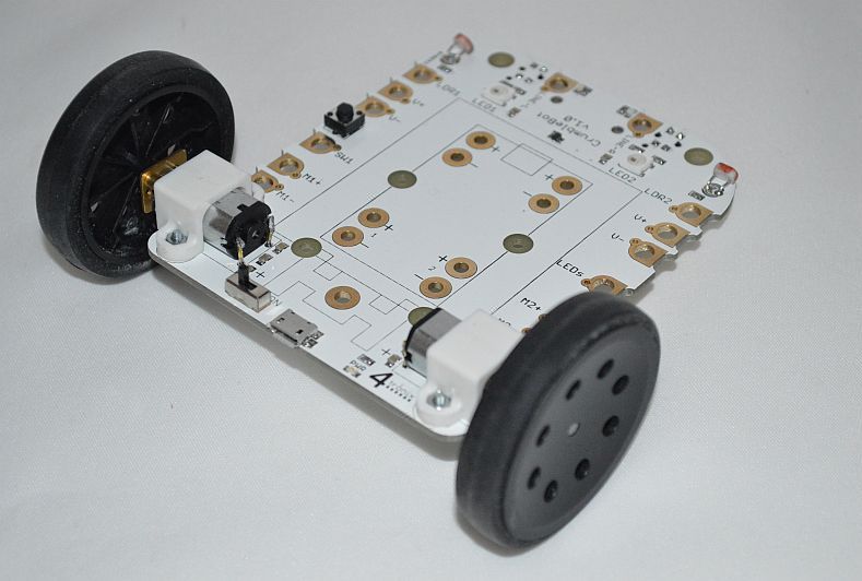
The wheels simply push onto the axle. Stop pushing when the axle is flush with the outside of the wheel
Step 3 – Fit the Front Caster

Use the 2 self-tapping screws in the bag with the caster to screw into the pre-assembled caster assembly. DO NOT overtighten
Step4 – Fit the Mounting Pillars for the Crumble

There are 6 pillars. The four at the back must be placed as shown as these connect the motor outputs from the Crumble to the motors on the CrumbleBot.
The front 2 pillars must be placed one next to a positive (+) and one next to a negative (-) connector. It doesn’t matter if you use both on the left side, both on the right, or one left and one right. Juste ensure you have one +ve and one -ve.
Screw the pillars in as tight as you can so they won’t move when the Crumble is attached.
Step 5 – Fit the Crumble

Use the remaining 6 small screws to fit the Crumble to the pillars.
Ensure that the USB connector on the Crumble faces the front of the CrumbleBot as shown in the photo above.
You have now built the CrumbleBot. That was easy wasn’t it!
Now to fit the battery pack – there are three options:
- If you have the USB rechargeable battery pack, go to Step 10
- If you have the standard 3xAA battery holder with wire leads, then go to Step 6B
- If you have the new “Wire-Free” 3xAA holder, then continue here with step 6A
Step6A – Fitting the new “Wire-Free” 3xAA Holder

The new battery holder is fitted to its own black PCB with switch, indicator LED and fuse.
This complete assembly screws to the top of the 20mm pillars supplied.

Power is taken from the bottom of the pillars using the supplied “Battery Adaptor” PCB that is fitted underneath the main PCBA
Step 7A- Fit the 20mm Mounting Pillars and Battery Adaptor

Use the 2 longer 6mm CSK screws included with the battery adaptor to fit the front of the battery adaptor into the small pillars holding the Crumble
Use the long 8mm screws to fit the rear of the battery adaptor to the 20mm pillars
Now go to Step 8
Step 6B – Fitting the standard 3xAA Battery Holder with Wires

Check you have the following:
- 3xAA battery holder with micro-USB connection
- 2 long pillars: 20mm, M2.5, Female-Female
- 4 long scres: 8mm, M2.5, countersink head
Step 7B – Fit the Battery Mounting Pillars

The two pillars fit directly behind the Crumble as shown in the photo above.
Screw the pillars as tightly as possible so they won’t move when the battery holder is attached
Step 8 – Attach the 3xAA Battery Holder

Use the 2 remaining 8mm screws to screw the battery holder to the mounting pillars.
Fit it with the cable to the front of the CrumbleBot, then the extra length of cable can pass over the battery holder instead of trailing on the ground
Step 9 – Plug in the USB Connector

You have now completed your CrumbleBot with AA battery pack. Time to learn how to code!
Step 10 – Attaching the USB Battery Holder

Check you have the following:
- White plastic clip for holding the battery
- USB battery stick (various colours may be supplied). These are 2600mAH batteries
- Fixing screw: 12mm, M3, countersink head
- Fixing nut: M3
- USB to micro-USB cable (various colours/styles may be supplied)
Step 11 – Attach the Mounting Clip

Pass the screw through the plastic pillar, through the CrumbleBot PCB and into the nut. Tighten well
Twist the clip if necessary to make it point forwards
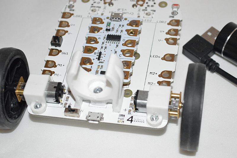
Step 12 – Fit the USB Battery Pack

Push the USB Battery Pack through the clip from the front. Do not attempt to clip it in from above as it is very stiff.
Use the USB cable to connect the Battery Pack to the USB connector on the CrumbleBot

You have now completed your CrumbleBot with USB Battery Pack! That was easy wasn’t it? Let’s go and code it
Step 13 – De-Slipping the Crocodile Clips
The crocodile clips can be very slippy within the soft rubberised covers which can make them difficult to grip and clip onto things. We therefor provide some rubberised tubular sleeves.
- Cut each sleeve in half, so you have 4 pieces
- For each end of the 2 crocodile leads:
- Slide off the rubberised cover
- Push on a half-sleeve onto the exposed metal tab
- Slide the rubberised cover back on
- If you clip the crocodile clip to something first, then it is easier to remove and replace the rubber cover
Coding for your CrumbleBot
** Please note that only the motors are permanently connected. All other features require one or more croc clips (included) to be connected from the Crumble to the Crumblebot. This allows more features to be included than can be active at any one time.
1 – Know your CrumbleBot

The CrumbleBot looks simple, but it has an amazing array of features just waiting to be used by you and your Crumble:
- Micro-USB connector. This is the power input to the CrumbleBot and powers everything on the CrumbleBot including the Crumble. It cannot be used to program the Crumble
- On-Off Switch. This, er, switches the power on or off. When the power is on then the Blue indicator LED near the switch is lit
- 2 micro metal gear motors that can be driven independently at varying speeds in either direction, making it easy to go forwards, backwards, spin on the spot or do sweeping turns – all at your command. The motors are permanently connected to the Crumble via the small mounting pillars. You do not need to use croc clips to operate them
- 2 line sensors with indicator LEDs. These are placed at the front of the CrumbleBot and detect whether a black line or a reflecting surface is underneath. You can use black insulation tape as your line and stick it directly to the floor or desk. Or you can print out a thick black line on paper (make sure the line is about 1cm wide). If a line sensor detects a line, then the corresponding indicator LED (Red for left, Green for Right) will come on. These provide DIGITAL INPUTS to the Crumble. HI for detecting a line; LO for a reflecting surface
- 2 light sensors. These are ANALOG INPUTS to the Crumble and will give a varying value between 0 (totally dark) and 255 (very bright) depending how bright the light shining on them is. Use these to search out the brightest place to be, or the darkest place to hide!
- 2 Sparkles. When connected directly to the Crumble these are Sparkle 0 (labelled LED1) and Sparkle 1 (labelled LED2). You can control the brightness and colour of these Sparkles independently – why not use them to show what your CrumbleBot is doing?
- Small tactile switch. This is a DIGITAL INPUT to the Crumble. When pressed it is HI, otherwise it is LO
2 – Let’s Get Moving

The program above is all you need to make your Crumble move Forward. Motor1 is the Left Motor; Motor 2 is the Right Motor. If they both move forward, then the CrumbleBot with move forward in a straight line*
* “Straight Line”. All motors are very slightly different from each other. This means that even if you set the same speed for each motor, they will not move at exactly the same speed and the CrumbleBot will turn to one side or the other. You can correct for this when it is important (it isn’t always important at all) by setting a slightly different speed for each motor. For instance, we found that the CrumbleBot is moving slightly to the left, so we speed up the left motor to 80% like this:

You can set the speed of each motor independently to between 0 and 100%. You will find that the motors won’t have enough power to turn if the speed is set too low; maybe less than 20% will be too low for the motors to move.
Setting the speed to 100% will move the motors at their fastest speed.
Note: You can actually set the speed of the motors to negative values. So setting it to go Forward -75%, is exactly the same as setting it to Reverse 75%
If you want the CrumbleBot to spin left, then set the left motor to Reverse and the right motor to Forward, as shown below:

If you want the CrumbleBot to spin right, then do the opposite: set the left motor to Forward and the right motor to Reverse:

3 – Let There be Light!
Let’s get the Sparkles on the Crumble Bot going.
First we need to connect the D output of the Crumble to the LEDs input on the CrumbleBot

Then the Left is Sparkle 0 and the Right is Sparkle 1
The we can use the Sparkles commands in the Crumble software to flash them. The program below flashes them Blue alternately, Left then Right then Left then…

4 – Follow That Line!
The CrumbleBot has 2 line follower sensors on the underneath at the front. These have associated LEDs which light up when a black (non-reflective) line is detected. Red for Left (Port) and Green for Right (Starboard). These LEDs are active any time the CrumbleBot is powered up; they do not require any software on the Crumble.
To use the line follower sensors, you must connect them to the inputs you want to use. In this demo, we will use inputs B and C. See the photo below for the connections:

A basic program for this is shown below. If the left sensor detects a line (if B is Hi) then the robot should turn Left. If the right sensor detects a line (if C is Hi) then the robot should turn right. Otherwise it should go forward

You can easily extend this program so that it stops, or turns round if both sensors detect a line, or you can make rules for what will happen at a junction
5 – Finding the Light
The CrumbleBot has 2 light dependent resistors (LDRs) at the front left and the front right. These produce analog values from 0 to 1023. 0 means there is no light at all, whereas 1023 means there is lots of light. In practice you will only see readings well within these 2 extremes.
Let’s use the inputs B and C again, but this time we will read the analog values. Wire up the CrumbleBot as shown below:

We can use a similar program to the line follower. What we want to do is turn the robot to the side that has the most light. Because the light sensors can vary a lot, we must be careful that we don’t turn the robot every time there is a very slight difference in light levels, otherwise it would spend all its time turning and never move forward much. So we create a guard band in the software and make sure the light levels are sufficiently different before we decide to turn the robot. This is why we compare the X and Y variables and make sure there is a difference of at least 10, before turning

You will note that there is a delay of 100 milliseconds at the end of each loop. You can experiment with different speeds, guard bands and delays to see which is fastest to get the robot to a specific spot near the light
Why not try and change the code so the robot finds the darkest place to hide?
6 – Check that Switch!
The CrumbleBot has a little switch on it that you can use to change what is happening in the program or simple to react by switching on LEDs.
Let’s start by connecting the switch to input B

Now we can write a program that checks to see if the switch is pressed. It will be Hi if pressed, or Lo if not pressed.
This simple program turns the left motor on when the switch is pressed and stops it when the switch is released

7 – Adding Extra Sensors – Obstacle Avoider
The CrumbleBot has 2 holes near the front that you can use to add sensors. In this section we are using the microswitch kit to add obstacle sensors to the CrumbleBot.
Because these sensors are not part of CrumbleBot itself you will have to connect power as well as the signal to each microswitch. So you will need 4 short croc clips altogether, 2 on each side as shown:

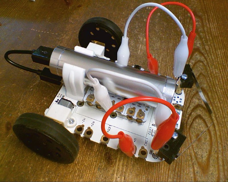
Connect the Power to the middle pin of the microswitch, and connect the B or C inputs to the “Normally Open” or NO contact. When the microswitch hits an obstacle then the corresponding input will be a Hi
For the Avoider program, which is similar to the line follower and light seeker, we make the robot reverse and turn when it hits an object. If the left microswitch hits, then we turn right, and if the right microswitch hits then we turn left. This gives us a chance of avoiding the object. The program also recognises when both switches hit an object together and stop the robot.

Understanding the Number Crumb
How the Number Crumb Works

The Number Crumb is designed to provide a simple display output for your Crumble. At this time, there is no native display for the Crumble and you have to give indications via the 4 outputs on the Crumble – perhaps lighting LEDs or sounding a buzzer.
The Number Crumb, however, is very different. There is a microprocessor on the Crumb which interprets the speed (PWM) information that you send to the motor on the Crumble.
Purchase Number Crumb here
Connecting the Number Crumb

- Connect power to the Number Crumb. The photo above shows Red for +ve and Black for -ve
- Then connect the motor outputs (either Motor 1 or Motor 2, it doesn’t matter which). Ensure that you connect the positive terminals together and the negative terminals together
- It doesn’t harm anything if you swap them over, but the Number Crumb with show negative numbers instead of positive, and vice versa
Programming the Number Crumb

To set a value on the Number Crumb, simply set the number you want into the “Motor Forward at nn %” block. Change nn to the number you want.
For example, the program above uses the variable x and starts at -30, then counts up to +100
The program below takes the input from an analog input (such as the Slider Crumb, Dial Crumb, or Light Sensor Crumb) and displays a value on the Number Crumb

Number Crumb Firmware
The Number Crumb has an ATMega328P on the PCB (under the display) which is configured as an Arduino Uno complete with bootloader. So you can reprogram the firmware to do whatever you want to do.
It has 2 digital I/O pins (D2 and D13) and then 10 pins are connected to the display via resistors.
There are 3 versions of the Number Crumb firmware in the field:
- Was released only for prototype Number Crumbs. This goes straight into number display mode when powered up
- Later prototypes and the first few production Number Crumbs had version 2. This displays “02” for a couple of seconds when powered up
- Currently shipping is version 3. This displays ” 3″ for a couple of seconds when powered up.
The changes between the versions are mostly to do with stability of number display
- The input signals from the Crumble, together with the resolution of the onboard counter leads to variations in the number displayed which was not always the same as the number input into the Crumble’s motor
- Version 2 made big changes to this accuracy, but still had some numbers that were difficult to display reliably. In addition, it was quite slow reacting to new numbers which meant that it was not able to keep up with the counting program above. There was also a lot of flicker for numbers -100, 0 and +100
- The algorithm for counting has been improved so the resolution is better and the averaging and display algorithms have been more tightly integrated so that the flashing/flickering disappears. Leading zeros have been suppressed, which allows a minus sign to be used for numbers -1 to -9 instead of the dots.
The software essentially times the edges of the motor drive signal. PWM (Pulse Width Modulation) sends a pulse at a fixed frequency and varies the width of the pulse to increase or decrease the speed of the motor. The Number Crumb accurately times the edges and can work out from that what number was set in the motor control block of the software. Version 1 or the firmware would work with most PWM drivers, but version 2 and 3 are increasingly tuned to work very closely with the Crumble PWM and would probably give inconsistent or nonsensical values with other PWM drivers.
Programming the Number Crumb
There are six header holes on the Number Crumb that allow you to directly plug in a suitable CP2102 and reprogram the Crumb using the Arduino IDE. Set your board type to Uno and ensure you select the CP2102 as your port/device.
If you have firmware version before 3 and want to upgrade it, you can either do it yourself (contact us for the program) or send it back to us and we will reprogram it for you.
Assembling Pi2Go
Assembling Pi2Go

Pi2Go is the pre-soldered big brother of the popular Pi2Go-Lite kit. Assembly is simply a matter of screwing together and plugging connectors.
Overview of Steps
- Fit the front caster and line following assembly
- Fit the mounting pillars for your chosen Raspberry Pi
- Attach the motors
- Fit the Raspberry Pi
- Fit the battery box
Step 1 – Fit the Front Caster and Line Follower Assembly
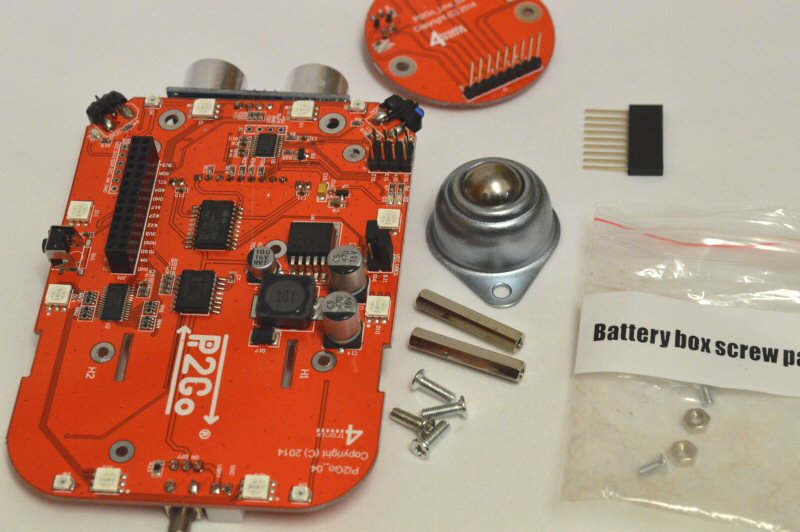
You will need the M3 screws, 27mm pillars, ball caster and 9-way extended header and the line follower PCBA

Fit the 2 pillars to the front of the Pi2Go using 2 of the M3 screws

Carefully push in the 9-way header, then attach the line follower PCBA
<photo missing>
Use the remaining 2 screws to attach the ball caster. If there is a bit of slack in its position, ensure that it doesn’t touch the pins of the connector
Step 2 – Fit the Mounting Pillars for Raspberry Pi
For the older Raspberry Pi models with a 26-pin GPIO connector, you will need to fit 2 pillars. For the A+, B+ and RPi 2B you should fit 4 pillars
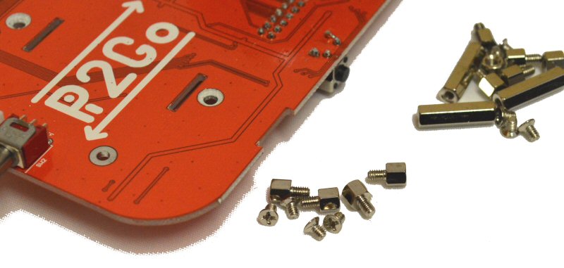
Fitting the pillars is a 2 step process: 1) fit the small 5mm pillars, 2) screw in the 16mm pillars.

The photo above shows the 5mm pillars in the mounting positions for A+, B+ and RPi 2B models
Use the very small 4mm screws to attach all the pillars. Note that the holes under the motors have been countersunk to allow the motors to sit flat onto the PCBA

The photo above shows the 16mm pillars added for the correct height (A+, B+, RPi 2B)

The photo above shows the 2 pillars in place ready for the Model A or Model B
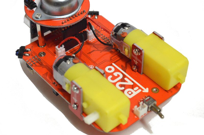
Step 3 – Attach the Motors

For this you will need 25mm screws, nuts and the motor mounts

Push the screws through the outer motor mount, then the motor, then the inner motor mount and attach to the nuts
Step 4 – Fit the Raspberry Pi

Using the extended header (in the bag with the battery box), connect the Pi onto the Pi2Go PCBA.
NB. Ensure that the mounting holes line up with the pillars! If they don’t then the Pi is not fitted correctly and may be damaged.
The above photo shows the RPi 2B in place. The A+ and B+ fit the same way.
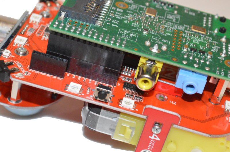
This photo (above) shows a Model B
Step 5 – Fit the Battery Holder

Use the 5mm pillars to attach the Raspberry Pi firmly to the mounting pillars. Use 2 or 4 pillars depending on your model of Pi (RPi 2B shown above)
For the Model A and Model B, you can now screw the battery holder directly to the 2 supporting 5mm pillars
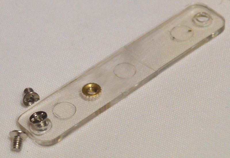
For the A+, B+ and RPi 2B you will need to fix the support plates in place first
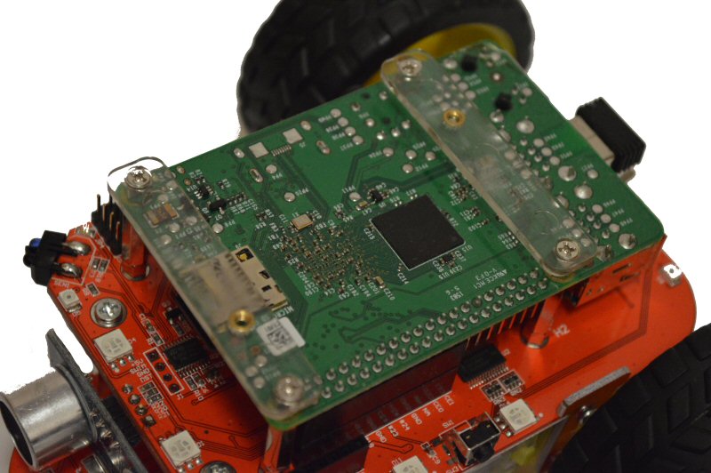
Ensure the one at the front has the threaded insert on the left of the Pi2Go and the one at the rear on the right. Also ensure that the wide parts of the mounting holes are at the top so that they can accept the heads of the screws.
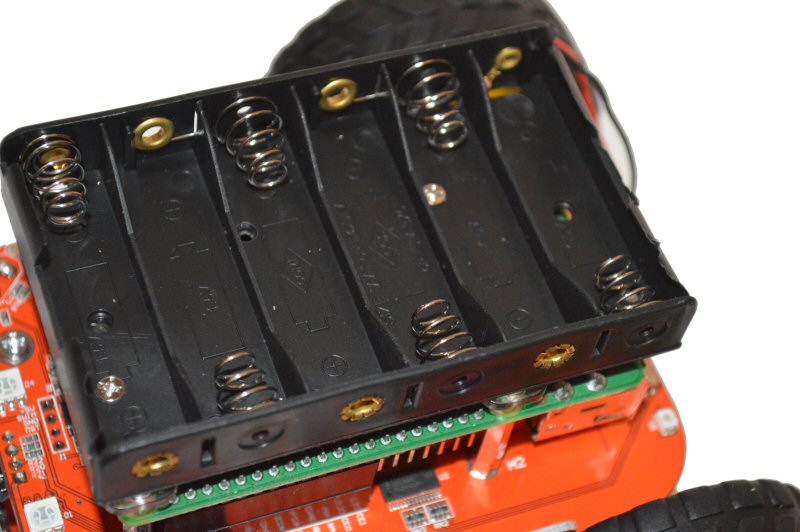
Finally, screw in the battery holder using 2 of the very small 4mm screws
Now you can add batteries, software and enjoy!
Crumbs for Crumble Controller
Crumbs – Addon Components for your Crumble Controller

Purchase the Crumbs Here
Also check out our Crumble Starter Guide
Download a PDF of this guide complete with Code examples from here.
Style of Crumb
- Analog input: These Crumbs are coloured Yellow and provide a continuously varying input for the Crumble which can be read and used with the A. B, C and D connections
- Slider
- Dial
- Light Sensor
- Motion Sensor
- Digital input: Blue. These Crumbs provide a simple On/Off input to the Crumble controller. Again would be used with the A, B, C and D connections
- Button
- Magnetic Hall Effect Switch (previously Reed Switch)
- Proximity Sensor
- Dual Capacitive Touch Sensor
- PIR sensor
- Ultrasonic distance sensor
- Analog output: Red. These Crumbs allow the Crumble to continuously vary the device: speed of the motor, brightness of the Sparkles, Number shown on the display, position of the servo
- Motor
- Number Display
- Servo
- Digital output: Black. These Crumbs can be set either On or Off by the Crumble
- Traffic Lights
- Buzzer
Using Crumbs
Most Crumbs require a 5V Power and Ground connection to be made before they work fully. Sometimes this is to power the on-board electronics and sometimes, simply to ensure that the indicator LED works as expected.
The Crumbs are designed so that the Power and Ground (5V and 0V) can be applied to either the left or the right side. It doesn’t matter which you use. You can then use the opposite side to take the power to any other Crumb that you are using, as shown in the picture below:

We recommend using short crocodile clips to join the Crumbs together as it reduces the amount of wiring considerably and the whole experiment becomes clearer to understand
Although the Crumbs are generally protected against connecting power on the wrong way round, or onto the wrong pin, it is recommended that you use some sort of colour coding so that the children can see how the positive power flows (using Red wires) or the negative with Black wires. You can use Green as an alternative to Black if you run out, but Yellow, White and Green are good colours to use for the general purpose inputs/outputs or motor outputs.
Where there are 2 crocodile lead connection pads next to each other on a Crumb (or indeed the Crumble) the two small holes that form part of the pads are designed to be exactly 5mm apart so that a standard 2-pin 5mm screw terminal can be soldered on. This allows you to use standard wires of exactly the correct length that are simply screwed into the terminal blocks as shown below:

Analog Input Crumbs (Yellow)
SLIDER
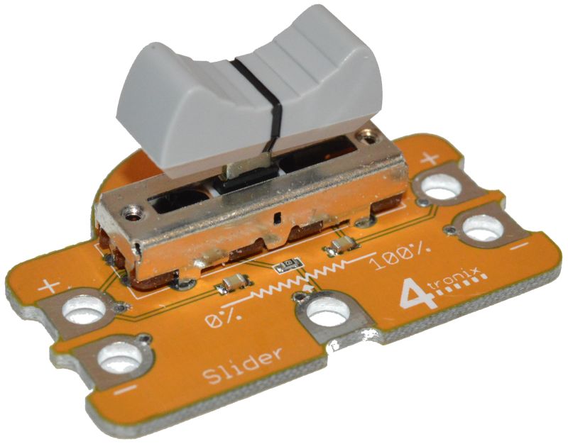
This requires Power and Ground to be connected and the output connected to A, B, C or D. The analog value read will be in the range 0 to 255, though in practice the power is not at 5V so the top end number will be lower
Sliding the slider to the left will give a value of 0, to the right will give the maximum number (probably 200 to 255)
The program below reads the value from the Slider Crumb connected to Input A, into the variable X. You can see the value being displayed on the left: x = 226

DIAL
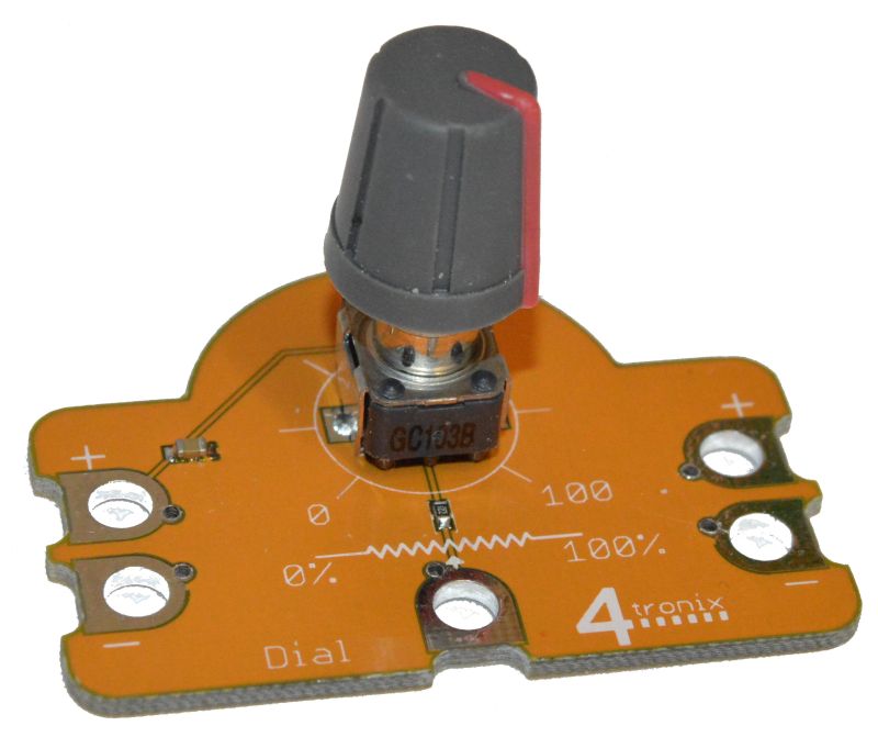
This requires Power and Ground to be connected and the output connected to A, B, C or D. The analog value read will be in the range 0 to 255, though in practice the power is not at 5V so the top end number will be lower
Turning the Dial anti-clockwise will give a value of 0, turning it clockwise will give the maximum number (probably 200 to 255)
The program below uses the value read from the Dial Crumb connected to Input A to set the speed of Motor 1. Note that the maximum value for motor speed is 100, so we divide the value from the Dial Crumb by 3 to be sure it fits into this range.

LUX/LIGHT

This requires Power and Ground to be connected and the output connected to A, B, C or D. The analog value read will be in the range 0 to 255, with 0 being total darkness and 255 being extremely bright.
Covering the light sensor completely will reduce to the minimum value and shining a bright light on it will achieve the maximum
The program below uses the value from the Light Sensor Crumb to set the brightness of the Red element of Sparkle 0. So in a dark room, the Sparkle won’t be as bright as in a bright room.

MOTION

This requires Power and Ground to be connected and the outputs connected to A, B, C or D. The analog values read will be in the range 0 to approximately 125
You can tilt the board in X, Y or Z axis and the appropriate output will change its value. Maybe you can use this to steer a robot?
The program below extends the program for the Light Sensor Crumb by using all three axes of the Motion Sensor to set the three colour elements (Red, Green and Blue) of the Sparkle. So twisting and turning the Motion Crumb will change the brightness and colour of the Sparkle.

Digital Input Crumbs (Blue)
BUTTON

This requires the Power to be connected in order for the button to operate. In addition, you should connect the Ground so that the indicator LED operates.
When the button is not pressed, the output is 0 (Low) and the indicator is Off
When the button is pressed, the output is 1 (High) and the indicator is On
The program below starts Motor 1 running when the button is pressed and stops it when the button is released:

ULTRASONIC DISTANCE SENSOR

This requires the Power and Ground to be connected in order for the sensor to operate. You can connect the centre output to any of the 4 Crumble inputs (A, B, C or D).
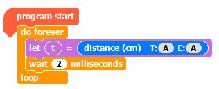
Both the Trigger (T) and the Echo (E) are connected to the same pin, so use the same pin letter in both for the distance block.
Also, it is important that there is sufficient delay between repeated readings for the sensor to recover
The program below repeatedly reads a value and you can see it on the Crumble app by watching variable t:
MAGNETIC HALL EFFECT SWITCH

This requires the Power to be connected in order for the Hall Effect switch to operate. In addition, you should connect the Ground so that the indicator LED operates.
When a magnet is not present, the output is Low)and the indicator is Off
When a magnet (eg. a fridge magnet) is brought towards the sensor, the output is High and the indicator is On
The program below counts the number of pulses received from the Magnetic Switch Crumb. Maybe the magnet is on a wheel spinning round past the Crumb and this is counting the revolutions of the wheel?

PROXIMITY SWITCH
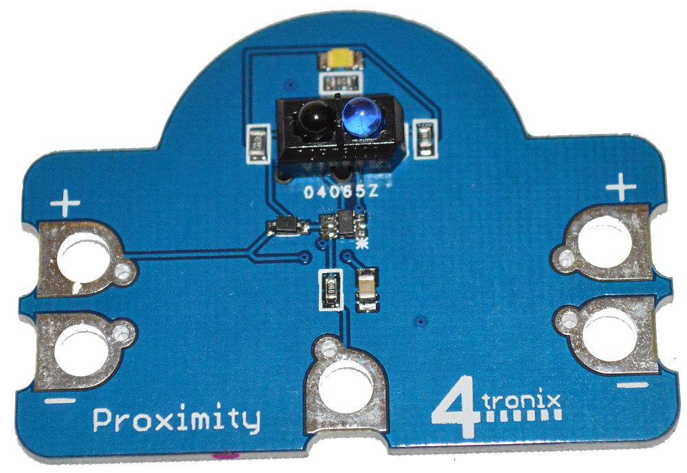
This requires the Power and Ground to be connected in order to operate.
When there is no object near the sensor, the output is 0 (Low) and the indicator is Off
When an object (eg. a hand) is brought above the sensor, the output is 1 (High) and the indicator is On
The sensitivity is set such that a finger or hand would trigger it within about 2 to 3 cm. A reflective white card would be about 10cm
The following program waits for the trigger from the Proximity Crumb connected to input A then switches on the Buzzer connected to output B for 1 second

CAPACITIVE TOUCH SWITCH

This requires the Power and Ground to be connected in order to operate.
When nothing is touching the sensor pads, the outputs are 0 (Low) and the indicator is Off
When a finger touches the sensor, the output is 1 (High) and the indicator is On
You can attach other objects such as pieces of fruit to the external inputs – give the system a minute or so to settle down (or remove and replace the power to reset it) after you change the connections
The program below uses the 2 outputs from the Touch Sensor Crumb connected to Inputs A and B to control 2 motors and steer a robot left or right

PIR (PASSIVE INFRARED) SENSOR
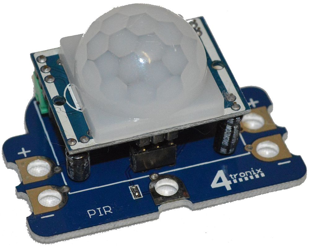
This requires the Power and Ground to be connected in order to operate.
When nothing moving is detected, the outputs are 0 (Low) and the indicator is Off
When movement is detected , the output is 1 (High) and the indicator is On
The program below flashes lights (on Output B) and Sounds a Buzzer (on Output C) when movement is detected

Digital Output Crumbs (Black)
TRAFFIC LIGHTS

This requires the Ground to be connected and the Red, Amber and Green connections made to your choice of A, B, C or D on the Crumble
Setting the appropriate output on the Crumble to Hi will light the LED on the Crumb as well as the related LED on the Pi-Stop if one is plugged in
The following program runs a basic traffic light sequence with Red connected to A, Amber to B and Green to C

BUZZER

This requires the Ground and Power to be connected as well as the input connection made to A, B, C or D on the Crumble
Setting the output on the Crumble to Hi, will sound the Buzzer and light the indicator LED. Note that if the power isn’t connected, the indicator LED will still light, but the buzzer won’t sound.
The follow program plays a sort of Morse code SOS on the Buzzer Crumb connected to output A. (in fact it just does the first ‘S’ otherwise it would be a bit long)

Analog Output Crumbs (Red)
MOTOR

This requires the two terminals on the Crumb to be connected to the Motor1 or Motor2 outputs on the Crumble
There are 3 sets of the motor connector pairs. They are all identical, but make it easier to connect from different sides if for instance you use them to make a robot or similar
Setting the Motor Speed to 100 will turn the motor approximately 2 turns per second (120 rpm). The motor will stop turning if the speed setting is below about 20
If you connect + to + and – to – from Crumble to Motor Crumb, then FORWARDS = anticlockwise and REVERSE = clockwise.
The following program controls 2 motors to move a vehicle Forwards, Backwards, Spin Left, Spin Right and Stop continuously.

NUMBER
This requires Power and Ground to be connected as well as M+ and M- to be connected to the Motor1 or Motor2 outputs on the Crumble
Setting the motor speed to any number will cause that number to be shown on the display
Forwards is shown directly (eg “75”) but Reverse adds the decimal points so will show “7.5.”
See this blog entry for more information on using this Crumb
The program below simply counts up from -30 to +100 continuously:

SERVO

This requires Power and Ground to be connected as well as the centre connection to one of the outputs on the Crumble
Use the Servo command in the Crumble software to set the position of the servo
** Ensure that you do not try and set the servo outside the range of -90 to +90 or unpredicatble movements may occur
The following program uses the Slider or Dial Crumb connected to input A to adjust the position of the servo on Output B:

Crumble Controller – Coding & Electronics for Primary Classrooms
Crumble – Easy Peasy, Lemon Squeezy
Related Posts:

The Crumble controller is a tiny circuit board, only 33 x 52mm that allows young children (and their teachers) to quickly and very easily learn coding and some simple electronics.
Physically, the Crumble is connected to other components using crocodile leads (“croc clips”), whilst in the software (which runs on a PC and Mac – Linux is coming soon) everything is done visually using drag and drop or simple clicks for selections.
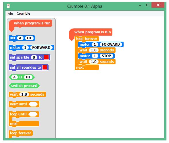
Simple drag the elements you want onto the stage, click on the selections (eg On and Off, Motor1 or Motor2) and press Go. The program is sent directly via USB to the Crumble and starts to run immediately. Even better, the Crumble never forgets its program, so you can power it back up next day or even next year and it will start running the last program downloaded to it.
The hardware is designed very cleverly so the 4 connections labelled A, B, C and D can be either Inputs or Outputs and they will automatically change based on what you use them for in the program. No need to worry younger children with setting things up first, Crumble just works out what they want to do and does it directly.
What Do I need to Get Started?
Ideally, purchase one of our starter kits and include a battery holder. What you need is:
- The Crumble controller itself
- Micro-USB cable
- Optionally – Something to use as an output (eg an LED or two, a motor, Sparkle, etc.)
- Optionally – Something to use as an input (eg. a switch or a light sensor)
- If you want to drive Sparkles or motors, then you will need a battery holder which you can connect to the Crumble using croc clips
- Download the software (PC or Mac available now, Linux coming soon) from here
- We are developing a number of “Crumbs” to use with the Crumble. Currently available or under development are:
- Sparkles – full RGB LEDs
- Slider – Analog input slide controller
- Dial – Analog input rotary control
- Lux – Analog input light sensor
- Motion – Analog input 3-axis motion sensor
- Button – Digital input press button
- Reed – Digital input magnetic reed switch
- Proximity – Digital input proximity detector
- Touch – Digital input touch pads
- Motor – Analog output DC motor
- Number – Analog output Numerical display
- Servo – Analog output positional servo
- Traffic – Digital output LEDs in Red, Amber, Green with PiStop support
- Buzzer – Digital output Buzzer with indicator LED
Visit THIS LINK to learn more about our Crumbs
Hello World – Flashing an LED
You can connect the Crumble outputs (A, B, C and D) directly to LEDs to turn them on and off. Remember the LEDs only work in one direction, so make sure you connect the long lead (positive) to the output terminal and the shorter lead (negative) to the ground terminal (-). You won’t damage anything by putting it the wrong way round, it just won’t operate.

In the photo above, a blue LED is connected from A to the long lead (using the Yellow croc clip) and from the short lead to Ground – terminal (using the Green croc clip)
The program to flash it forever looks like this

Setting output A to HI, switches on the LED. Setting to LO switches the LED off. How simple is that?
Now extend this by connecting different colour LEDs to the different outputs (B, C and D) and see if you can make a traffic light sequence!
Doing something with an Input
There are 2 types of input devices that you can use:
- Digital inputs (such as a switch) that can be On or Off
- Analog inputs (such as a light sensor) that can be any value from 0 to 255. (these numbers are arbitrary and chosen by the Crumble designers to match the internal hardware. The numbers do not mean anything in the “real world”, except that 0 is the smallest value and 255 is the largest value)
In the 4tronix standard starter kit we include an LDR (Light Dependent Resistor) which is an analog input device. For this to operate, one end (it doesn’t matter which end) is connected to a positive output and the other end goes to the input. For the positive output you can use one of the (A, B, C, D) terminals – or the 5V (+) terminal if you have power connected from a battery pack. Note that the + terminal is not powered from the USB input, only from a separate battery pack.
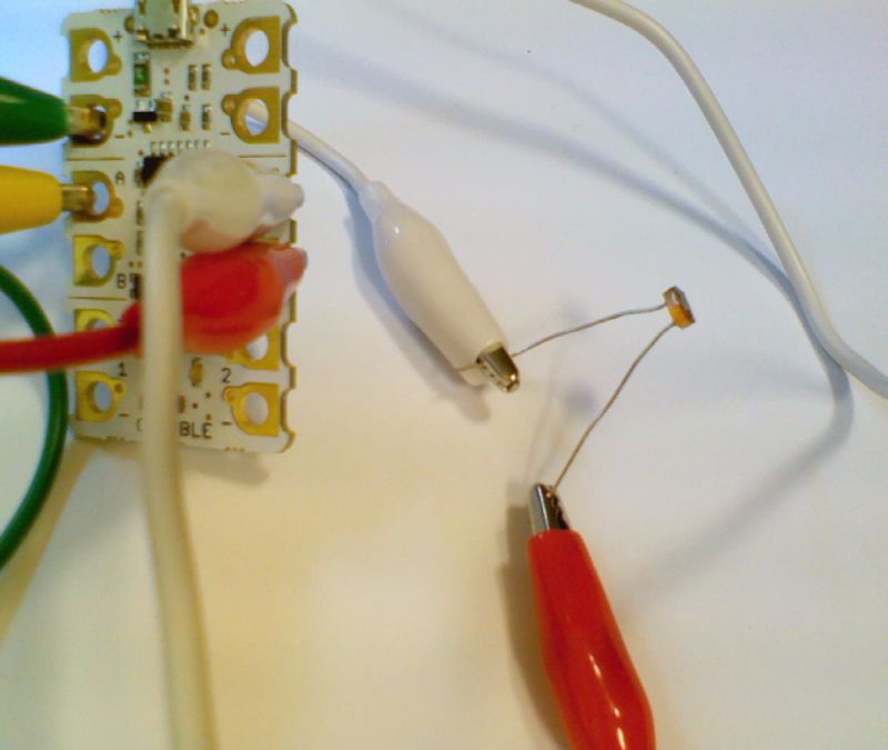
Here red and white croc clips are connected between C, D and the two leads on the LDR. The yellow and green croc clips are still connected to the blue LED from the example above.
The following program uses the analog values (between 0 and 255 remember) to set the delays in the flashing loop. The smaller the number, the faster the LED flashes. The number is smallest when the LDR is darkest – higher numbers for brighter lights.

The first command is to set output D to HI. This provides the positive signal for the LDR.
Note that we have used the “wait … milliseconds” block instead of “wait … seconds”. Waiting 255 seconds between flashes might be too long!
The time to wait between flashing HI and flashing LO is simply the analog value of the LDR. The brighter the light, the bigger the analog value and the longer the flashes.
Driving the Sparkles
Sparkles are individual RGB (Red, Green, Blue) LEDs that can be connecting in a long chain (up to 32 with the current software) and each can be set to a different value. These are also known as “neopixels”. Sparkles require a 5V power connection which can be from the + terminal on the Crumble (if a battery pack is connected) or from one of the A, B, C outputs set to HI. If using one of the A, B, C outputs then you can only use 1 or 2 Sparkles as they cannot provide enough power for more.

In the photo above, we have used output C to connect to the Sparkle’s power + input. The data input of the first Sparkle in the chain must be connected to the D output on the Crumble. This first Sparkle is called Sparkle 0, the next is Sparkle 1 and so on. Each Sparkle must be connected to power and Ground: use the + and -terminals from the previous Sparkle for this. Each Sparkle also needs an input signal. The input for the first Sparkle is the Crumble D output, but after that use the output from one Sparkle and connect it to the input of the next in the chain


You can flash the Sparkles using a simple loop as shown above. Notice the first statement sets C to HI to provide power for the Sparkle. We only have one Sparkle in our chain, so this is Sparkle 0. You can select any colour you like for each Sparkle just by clicking on the coloured square.
Driving Motors
In our Super and Ultimate Crumble kits, we also include DC motors. Again, these can be driven directly by the Crumble, but you must have a battery pack connected for these to work. The mootors use Pulse Width Modulation (PWM) to adjust the speed. Instead of changing the voltage driving the motors, the amount of time that the motor is powered is varied. If it is powered 100% of the time it will go at full speed, but if only powered 50% of the time it will go about half speed (actually, it isn’t quite that, but close enough).
So connect one side of the motor to the motor + terminal on the Crumble (eg. Motor 1) and the other side of the motor to the motor – terminal as shown.

This program loop runs forever and makes motor 1 move forward for 1 second, then backward for 1 second
Crumbs
Slide Crumb – Analog Input

The Slide Crumb is Yellow – this means it is an analog input Crumb
In the software, you can read analog inputs using the  method. This gives a number from 0 to 255 that you can use to set the brightness of Sparkles, the speed of a motor or the rate of flashing of LEDs for example.
The code below sets the brightness of the Red component of a Sparkle

And this one sets the speed of the motor to vary with the position of the slider. Note that the motor speed must be between 0 and 100, so we divide the analog value by 3 so that we don’t exceed the value

iBoost64 – What is It?
iBoost64 Overview

iBoost64 is a little board to boost input signals and electrically clean them up. It is designed solely for use with the Pirocon2

Pirocon2 has 8 bi-directional pins that determine the direction (input or output) using the strength of the drive signal applied to them. We have found that some sensors have insufficient drive strength to reliably convince the level shifters that they should behave as inputs. This has the effect of appearing to randomly react to or ignore inputs – especially with marginal sensors.
This little board can be plugged onto the pins of the Pirocon that you want to use as inputs only. With the board in place, the selected signals are always inputs and cannot be outputs.
Because the power and ground pins go all the way across the 8×3 connector on the Pirocon, you can plug the iBoost64 into any position even with only 1 set of three pins (although it wouldn’t be very stable like that)
The iBoost64 has 6 inputs which can either be high or low (hence the 64 because 2^6 is 64)
- 6 non-inverting schmitt trigger inputs
- high hysteresis so slow moving signals produce a nice clean edge for the Pi
- Enables weak sensor outputs to drive the Pirocon directly
- Wheel sensors on Initio can be driven with 5V as intended and plugged directly into the iBoost64

SmartBadge
SmartBadge – Flashing Pixels and Games for Geek Events

Designed in conjunction with Amy Mather @MiniGirlGeek
SmartBadge is a wearable that you can program to display patterns or messages, play games or just to blind anyone who comes too close
19 super-bright, full-colour individually addressable RGB neopixels arranged in hexagonal rings allow you to make fantastic dynamic patterns and exciting games
4 mini buttons give you control over menus, or game functions. You code, you decide!
Powered from a rechargeable lithium coin cell which lasts 45 minutes on a single charge whilst displaying patterns continuously.
Fast, simple and exciting way to start working with wearable computing

Features
- 19 RGB neopixels
- 4 buttons
- Arduino IDE compatible
- Rechargeable coin cell
- Power & activity LEDs
- On-off switch
- Fully soldered
Pre-Installed Demo Program
SW1 acts as the menu button. After a 5,4,3,2,1,0 countdown it shows a single purple LED. Pressing SW1 cycles through 1,2,3,4,5,6 LEDs lit. It times out after 5 seconds without a button press and runs the selected demo as below. You can press SW4 if you don’t want to wait the 5 seconds.
Press SW1 at any point to return to the menu
Individual Demos
- This is the default demo and just shows lots of pretty patterns
- Capture Pixels game. You have to press SW4 when the white LED is on to capture it. When you complete the level it starts again, but you get less time to do it
- Death Ray. Ray gun effect with super bright finale
- Bug Chase. My brother and I wrote this game at the end of the 70s/early 80s (ancient history). It sort of pre-dates pacman. You (Blue) have to visit every pixel to collect them, whilst being chased by a bug (Red). SW4 and SW3 move you around the hexagonal ring. SW2 moves you inwards. Collected pixels show green on the first level and subsequent levels get faster. On our original game we introduced a second bug on level 3, but I haven’t done that. This game is very hard!
Example software and neopixel library available from the 4tronix SmartBadge GitHub
PlayHAT
PlayHAT – Learn While Playing on Raspberry Pi

Purchase PlayHAT here
PlayHAT is a ready-assembled educational learning board with 9 full-colour neopixel LEDs with 4 big coloured buttons and a beeper
It is a great way to start learning about use of GPIO in either Python or Scratch. It’s very easy to program; use the python library or broadcast the ScratchGPIO message to set the LEDs to the colours and brightness that you want. The buttons and beeper can also be read easily in your software – each button is represented by a separate input pin. Switch the pin high and the beeper will sound.
The LEDs are in a 3 x 3 Matrix allowing:
- Randomising Dice
- Traffic Light simulator
- Simon game—remembering sequences)
- Use the full matrix for cool flashing patterns!
ScratchGPIO already supports PlayHAT in the development version.
To drive the neopixels in Python you can install our demo files from the 4tronix PlayHAT GitHub
Assembling Ultimate Initio Kit for Raspberry Pi with Pirocon
Ultimate Initio kit for Raspberry Pi

You should already have followed the instructions for assembling the chassis here.
In this section we will add the Pirocon2 controller, the obstacle sensors, line sensors and the pan/tilt assembly with ultrasonic sensor.
The (optional) iBoost64 is also used to boost incoming signal strength and resolve issues with marginal IR sensors, including the wheel sensors on the Initio
Quickstart Pinout Description
If you use the recommended iBoost64 input signal booster, then we can connect the 8 I/O signals as follows:
- Pin 7 – Left Obstacle sensor
- Pin 11 – Right Obstacle sensor
- Pin12 – Left Line sensor
- Pin 13 – Right Line sensor
- Pin 15 – Left Wheel sensor 1 (Optional)
- Pin 16 – Right Wheel sensor 1 (Optional)
- Pin 18 – Tilt Servo (Output – not connected to iBoost64)
- Pin 22 – Pan Servo (Output – not connected to iBoost64)
1. Fitting the Pirocon to the Raspberry Pi

Screw the support pillar to the underneath of the Pirocon. The position shown above is suitable for a Raspberry Pi Model B+, Model A+ or Raspberry Pi 2 Model B
Use the hole in the centre if using a Model A or Model B

Push the Pirocon carefully onto the GPIO pins of the Raspberry Pi, ensuring the pins are placed correctly as shown in the photo above

Connect the motor wires as shown. Red – Black – Black – Red
It won’t damage it if you connect them differently, but the example programs won’t go the direction that you would expect

Plug the Black/White cable with the DC Jack into the left-most pins on the switch PCB on Initio and the DC Jack end into the Pirocon as shown above.
Check all the wiring again very carefully, then now is a good time to see if the Pi powers up and you can control the motors.
Use 6xAA batteries. These should be good quality rechargeable batteries. We recommend Energizer Extremes or Eneloops
Connect a monitor, keyboard and mouse to the Raspberry Pi, plug in your SD card and switch on. The green light near the On/Off switch should turn on, the LEDs on the Pi should start flashing and the booting sequence should appear on the monitor. If not, switch off and double check the wiring.
Instead of using the batteries, you can plug a micro-USB cable directly into the connector on the Pi. This is an excellent way to get started and allows you to test everything (except the motors, which may turn but only slowly) without using batteries.
2. Mounting Obstacle Sensors

Check that each sensor has 2 mounting collars. Screw one onto the body of the sensor, leaving room at the front for the second one

Push the sensor through from the rear of the mounting bracket and screw on the second collar. Feed the wires up through the holes in the top plate

Repeat for the second side

Connect to the Pirocon2 (or the iBoost64 as below)
- Left sensor to Pin 7 (marked x07 or #04)
- Right sensor to Pin 11 (marked x11 or #17)
The wire colours from the obstacle sensor are:
- Red: 5V
- Black: Gnd
- White or Yellow: Signal
Make sure you connect them to the correct pins on the Pirocon or iBoost64

3. Mounting the Line Sensors

First, take the 30cm female-female jumper strip of 10 wires and split it into three strips:
- Brown, Red, Orange, Yellow (this is for the Ultrasonic Sensor)
- Green, Blue, Purple (this is for the Left Line Sensor)
- Grey, White, Black (this is for the Right Line Sensor)

Next, prepare the two Line Sensors and 2 of the 3x8PB screws as shown

Screw the line sensors in position as shown, using the screwhole in the middle of the circuit board

Connect the Green, Blue, Purple wire to the Left Sensor and the Grey, White, Black cable to the Right Sensor
** Note some sensors have the pins in order 5V, Signal, Gnd; other have them in order Signal, 5V, Gnd – make sure you know which wire colour is connected to which.
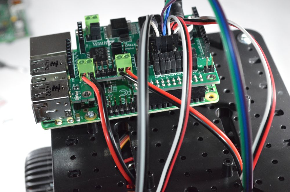
Connect the sensors to the Pirocon or iBoost64 (shown below)
- Left sensor to Pin 12 (marked x12 or #18)
- Right sensor to Pin 13 (marked x13 or #27)
4. Connecting the Pan/Tilt Assembly

This is now supplied fully assembled with the Initio Ultimate kit. If you have an unassembled one, then please visit the assembly instructions here (opens in new window)
Take 4 of the 2.0x6PB screws (these are the smallest ones in the packet and there are 6 of them)

Screw the base of the pan/tilt assembly to the upper plate in the position shown
Rotate the pan/tilt carefully left and right to access the screw holes
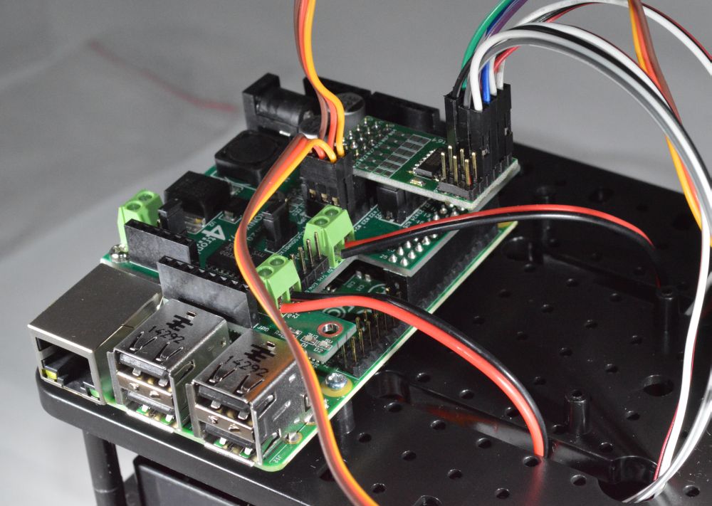
Connect the Pan servo (bottom servo) to Pin 22 (marked x22 or #25)
Connect the Tilt servo (upper servo) to Pin 18 (marked x18 or #24)
Note the colours of the servo wires and ensure they are connected correctly:
- Black: Gnd
- Red: 5V
- Orange or White: Signal
5. Connecting the Ultrasonic Sensor

For this you will need the mounting plate, saddle clamp and the final 2 of the 2.0x6PB screws used in step 4

Push the 4-way 30cm female-female cable that you made in Step 3 onto the top of the ultrasonic sensor:
- Brown: Gnd
- Red: Echo
- Orange: Trig or Ping
- Yellow: 5V or VCC

Screw the saddle clamp over the cable terminals as shown above

Clip the whole assembly to the front of the Pan/Tilt assembly as shown above
Note that you can purchase additional clip-on mounts so you could mount a camera on one and simply clip it off to change from Ultrasonic to Camera

Connect the other end of the cable into the ultrasonic pins located between the 2 motor terminals
Ensure that Brown is Gnd, and they are in the order as shown
The main build of your Ultimate Initio Kit for the Raspberry Pi is now complete.
6. Connecting the Wheel Sensors (Optional)
Note that the wheel sensors require additional code to operate properly that is not included in the python library.
It is recommended that you do not fit these until you are familiar with the operation of the rest of the robot.
If you want to fit them, use Pins 15 and 16 (marked x15, x16 or #22, #23 and note that the silk screen on the board has these swapped over)
For each Wheel Sensor, connect:
- Black to Gnd
- Red to 5V
- Orange or Brown to the selected pin (in fact, each wheel has 2 sensors that are slightly out of phase so you can get direction of travel from them, but you will then need 2 pins for each sensor)
It is recommended to leave the wheel sensor cables unconnected to start with