Win a Picon Zero and Raspberry Pi Zero!

Win a Picon Zero and Raspberry Pi Zero!

Competition Now Closed

  • You wanted analog inputs for your Raspberry Pi? – You got it!
  • You wanted to drive servos with no difficult software? – You got it!
  • What about driving WS2812 “neopixels” without kernel software that breaks every other release? – You got it!
  • Or maybe you want to get temperature from DS18B20-based sensors without lockouts and waits? – You got it!
  • Oh, and you want to drive a pair of 1.5A per channel DC motors using simple PWM settings? – You got it!
  • And of course, you want it for free? – You (maybe) got it!
  • Hang on, you want a Raspberry Pi Zero for free as well?? – You (maybe) got it!

We’re running a competition: simply retweet the competition tweet to be entered into the draw. On Sunday 3rd April, we will draw the winners:

  • 1st randomly selected, will receive a Picon Zero
  • 2nd randomly selected, will receive a Picon Zero and a Raspberry Pi Zero
  • 3rd randomly selected, will receive a Picon Zero and a Raspberry Pi Zero and a mini robot kit

Postage is FREE anywhere in the world

Competition closes 8pm BST on Sunday 3rd April. Winners will be announced shortly after.

Find out more about the Picon Zero here

Purchase Picon Zero here


 3rd Prize

prize01


2nd Prize

prize01    plus   prize02


1st Prize

prize01  plus  prize02  plus  prize03

Picon Zero – Intelligent Robotics for Raspberry Pi

Picon Zero – Intelligent Robotic Controller for Raspberry Pi

Purchase Picon Zero here

Worksheets now available – see the bottom of this page


Description

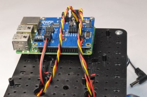
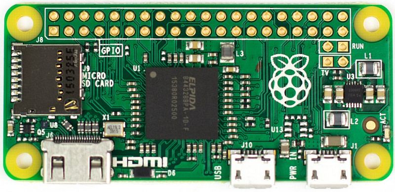
The Picon Zero is an add-on PCB for the Raspberry Pi. It is physically the same size as a Raspberry Pi Zero and so is ideal as a pseudo-Hat (pHat) for the Pi Zero. However, it can of course be used on any Raspberry Pi with a 40-pin GPIO connector. Currently that includes the A+, B+, 2B and 3B.

As well as 2 full H-Bridge motor drivers, the Picon Zero has a number of Input and Output pins that can be configured in a variety of ways, allowing you to easily add analog inputs or neopixel outputs to your Raspberry Pi without any complicated software and kernel specific drivers. It also provides an interface for an HC-SR04 ultrasonic distance sensor and opens up 5 GPIO pins from the Raspberry Pi for you to use as you see fit.

The Picon Zero is shipped with all components, including the headers and screw terminals, fully soldered. This saves you doing any soldering and allows you to use it directly from the box


Specification

  • Pseudo-Hat format PCB, 65 x 30 mm with gold plated pads and a ready-fitted 40-pin female header (if using a Pi-Zero, ensure you have soldered a male header in place)
  • 2 full H-Bridge motor drivers. Can drive up to 1.5A continuously (2A peak) per channel, at from 3 – 11V
  • Each motor output has both a 2-pin screw terminal and a 2-pin male header. You choose which to use, depending what connectors you have on the motors
  • The power for the motors can be taken from an external power source (3V to 11V) or from the Picon Zero’s own 5V
  • The Picon Zero’s 5V can be selected to be from the Raspberry Pi’s 5V line, or from a USB connector on the Picon Zero. This allows you to use 2 USB battery banks: one to power the Pi and the other to power the servos and motors on the Picon Zero
  • 4 Inputs that can accept up to 5V. These inputs can be configured as:
    • Digital inputs
    • Analog inputs (10 bits, 0..1023)
    • DS18B20
    • DHT11 (TBD)
  • 6 Outputs that can drive 5V and be configured as:
    • Digital Output (High or Low)
    • PWM Output (Pulse Width Modulation from 0% to 100%)
    • Servo (drives a standard servo through 180 degrees)
    • Neopixel WS2812 (Can drive up to 64 neopixels in a chain. Only available on output 5)
  • All Inputs and Outputs use GVS (Ground, Volts, Signal) 3-pin male headers. This is a common standard for 3-pin sensors and servos and allows direct connection without additional wires
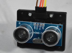
  • 4-pin female header that can connect directly to an HC-SR04 ultrasonic distance sensor. You can plug the sensor directly into this header for an ultra-compact, object avoiding robot
  • 8-pin female header for Ground, 3.3V, 5V and 5 GPIO signals allowing users to add their own additional features


Hardware Configuration

Picon Zero has 2 jumpers for setting the hardware configuration. Make sure you have them set in the correct positions for your requirements

  1. JP1 – Board 5V Selector. This jumper selects where to get the 5V power from for the Picon Zero Outputs. The options are:
    1. Jumper at the top between RPI and 5V. The 5V power for the board is taken from the Raspberry Pi 5V pins on the GPIO connector. With low power output devices and low power 5V motors, this allows you to power all devices with a single 5V power input to the Raspberry Pi
    2. Jumper at the bottom between USB and 5V. The 5V power is taken from the micro-USB connector on the Picon Zero. For higher power out devices, you can provide extra power through the micro-USB connector on the board
  2. JP2 – Motor Power Selector. This jumper selects where to get the power for the motors from. The two options are:
    1. Jumper at the top between Vin and MotorPower. The motors are driven from the 2-pin screw terminal. This voltage can be anything from 3V to 11V. Useful for motors that require a voltage different from 5V, or that require more current than is available on either of the USB input connectors
    2. Jumper at the bottom between 5V and MotorPower. The motors are driven from the board’s 5V power signal. Remember that this in turn can be selected to be either the Raspberry Pi or the micro-USB connector on the Picon Zero.


Programming

Raspberry Pi Setup

The Picon Zero is an I2C device, so you must ensure that your Raspberry Pi is setup to use I2C and smbus correctly:

  • sudo apt-get install python-smbus python3-smbus python-dev python3-dev
  • sudo nano /boot/config.txt
    • and add the following 2 lines to the end of the file:
    • dtparam=i2c1=on
    • dtparam=i2c_arm=on
    • Press <ctrl-x> and accept the default prompts to save the file
  • sudo reboot

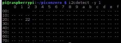
Plug the Picon Zero onto the Pi and run

  • i2cdetect -y 1

If all is well, you will see the Picon Zero showing up as address 22 as below:

i2cdetect


Python Example Installation

The Picon Zero is provided with a python library which allows very simple access to all the features in an intuitive and consistent manner. A separate small library handles the ultrasonic which is on a GPIO pin and not part of the onboard micro-controller.

Download the Picon Zero library itself  from here

You can also download directly both libraries and example files by typing the following into the terminal window. Open LXTerminal and type:

  • wget http://4tronix.co.uk/piconz.sh -O piconz.sh
  • bash piconz.sh

That will create a piconzero folder in your home folder, with the libraries and example files:

  • piconzero.py  library module for Picon Zero
  • hcsr04.py  library module for ultrasonic sensor
  • version.py prints the board type and firmware version
  • motorTest.py  tests the motor functions using the arrow keys on the keyboard
  • ioTest.py  demonstrates the use of an analog input (potentiometer on Input 0) used to control various forms of output
  • sonarTest.py  demonstrates taking distance readings if you have an HC-SR04 ultrasonic sensor attached
  • tempTest.py demonstrates reading the temperature from an attached DS18B20 sensor
  • 10linesTest.py  shows a simple 10 (or 11) line program that reads an analog input and outputs to various devices (same as ioTest.py but without some bells and whistles). Simply to show how easy it can be to use the Picon Zero
  • pixelTest.py  flashes all the attached neopixels from White to Off and back again
  • servoTest.py uses the arrow keys to move 2 servos (pan and tilt) and the G, H keys to move a third servo (grabber claw)


Basics of Programming Picon Zero

A python program should start by importing the library, eg.

import piconzero as pz

Notice that we have imported the whole library and then called it ‘pz’ for short. Now whenever we use any of the library functions we need to put the ‘pz.’ in front so python knows where to get the functions from.

Then you should call the initialising function to clear any previous settings that may have been left from a previous program closing untidily

pz.init( )

Now the library is set up and ready to go. Ensure you set the configuration required for each pin before using it (unless you are using the default configurations, when it is not necessary)

At the end of your program you should clean up the system and leave it in a nice state for the next program to use

pz.cleanup( )

The classified complete list of library functions follows


General Functions

  • init ( ): This clears all the Inputs and Outputs back to their default configurations, stops the motors, disables any servos and switches off neopixels. It also sets a few internal variables that allows the Picon Zero to keep track of what it is doing
  • cleanup ( ): This is pretty much the same as init() but is used at the end of the program to clean up all the outputs for the next program
  • getRevision ( ): This returns a list with board revision and firmware revision. It allows you to check whether the firmware is capable of any new functions (assuming new functions will be added later)


Motor Functions

  • forward (speed): Moves both motors forward at selected speed. Speed can vary from 0 to 100. (it can also be negative, which would cause the robot to reverse)
  • reverse (speed): Moves both motors in reverse ar selected speed. Speed can vary from 0 to 100 (can also be negative)
  • spinLeft (speed): Spins left on the spot at selected speed. Speed can vary from 0 to 100 (can also be negative)
  • spinRight (speed): Spins right on the spot at selected speed. Speed can vary from 0 to 100 (can also be negative)
  • stop ( ): Stops both motors
  • setMotor (motor, speed): This is the primitive motor function, called by all the others. Motor can be either 0 (Motor A) or 1 (Motor B). Speed can vary from -100 (full reverse) to +100 (full forwards). The speed number is a percentage.


Input Functions

  • setInputConfig (channel, config): This sets the configuration of the selected Input channel. There are 4 Input channels (0 to 3). The config parameter determines if the channel is:
    • 0: Digital (0 or 1) – this is the Default input configuration [there is a 3rd parameter for version 08 firmware and later: Pullup, set to False by default, but can be set to True which will provide a 10K internal pullup resistor on the selected channel
    • 1: Analog (0 to 1023) – read analog values from selected channel. 0V -> 0;  5V -> 1023
    • 2: DS18B20 [Available from firmware revision 06].  Reads a 18B20 temperature sensor
  • readInput (channel): Gets the value of the selected input channel. This will return:
    • o (False) or 1 (True) if the channel is Digital
    • A value from 0 to 1023 if the channel is analog
    • A temperature in centigrade if the channel is a DS18B20


Output Functions

  • setOutputConfig (channel, config): This sets the configuration of the selected Output channel. There are 6 Output channels (0 to 5) and these can be set as follows:
    • 0: Digital (Low or High) – this is the Default output configuration
    • 1: PWM (0 to 100% duty cycle)
    • 2: Servo ( 0 to 180 degrees)
    • 3: Neopixel WS2812B (individually address any pixel and set values of 0..255 for each colour). Only Output channel 5 can be set to this configuration value
  • setOutput (channel, data): Sets the output channel with the data entered – Digital, PWM and Servo data only.
  • setPixel (pixel, red, green, blue): Sets the selected pixel (0 to 63) with the selected red, green and blue values (0 to 255).
  • setPixel(pixel, red, green, blue, update): The optional parameter update (defaults to True), determines if the updated pixel data is updated immediately or not. Updating the pixel strip strip takes time, so if you are changing a number of pixels at once, it is best to switch off updates until they have all been changed, then use the updatePixels ( ) function
  • setAllPixels (red, green, blue): Sets all pixels with the selected red, green and blue values (0 to 255) [Available from firmware revision 07]
  • setAllPixels (red, green, blue, update): The optional parameter update (defaults to True), determines if the updated pixel data is updated immediately or not. Updating the pixel strip strip takes time [Available from firmware revision 07]
  • updatePixels ( ): Causes an immediate update of all the pixels from the latest data
  • setBrightness (brightness): Sets the overall brightness (0 to 255) of the neopixel chain. All RGB values are scaled to fit into this max value. Default is 40


 Worksheets

These downloadable worksheets take you through using various features of the Picon Zero in simple, self-contained, stages.

  1. Worksheet 01 – Setting up your Raspberry Pi for Picon Zero
  2. Worksheet 02 – Configuring and controlling motors
  3. Worksheet 03 – Getting Input from Buttons and Switches
  4. Worksheet 04 – First steps with analog inputs
  5. Worksheet 05 – Controlling servos
  6. Worksheet 06 – Controlling the brightness of LEDs (PWM)
  7. Worksheet 07 – Reading temperatures from a DS18B20
  8. Worksheet 08 – Driving WS2812B RGB LEDs (aka NeoPixels)


Assembling Initio using RoboHAT

Using RoboHAT with Initio
rh13

Click on any image to enlarge


You should already have followed the instructions for assembling the chassis here.

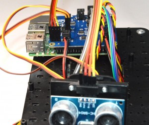
In this section we will add the RoboHAT controller, the obstacle sensors, line sensors and the pan/tilt assembly with ultrasonic sensor.

1. Fitting the RoboHAT to the Raspberry Pi
step01

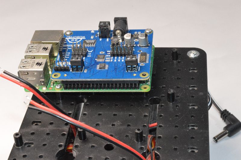
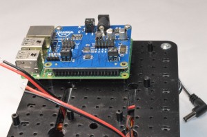
Screw one of the support pillars to the underneath of the RoboHAT at the front (under the RoboHat logo). Then plug the RoboHAT onto the Raspberry Pi.

Push the RoboHAT carefully onto the GPIO pins of the Raspberry Pi, ensuring the pins are placed correctly as shown in the photo above
step02

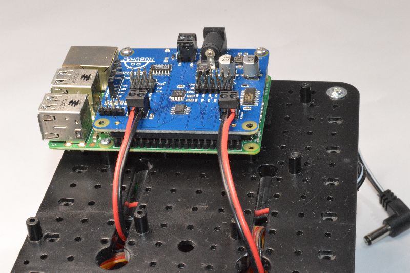
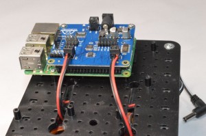
Connect the motor wires as shown. Red – Black – Black – Red

It won’t damage it if you connect them differently, but the example programs won’t go the direction that you would expect
ultpi_23

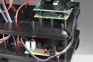
Plug the Black/White cable with the DC Jack into the left-most pins on the switch PCB on Initio and the DC Jack end into the RoboHAT as shown above.

There will be a spare cable with Red and Black wires. This is not required for the Raspberry Pi build and should be removed so the ends don’t short.

Check all the wiring again very carefully, then now is a good time to see if the Pi powers up and you can control the motors.

Use 6xAA batteries. These should be good quality rechargeable batteries. We recommend Energizer Extremes or Eneloops

Connect a monitor, keyboard and mouse to the Raspberry Pi, plug in your SD card and switch on. The green light near the On/Off switch should turn on, the LEDs on the Pi should start flashing and the booting sequence should appear on the monitor. If not, switch off and double check the wiring.

Instead of using the batteries, you can plug a micro-USB cable directly into the connector on the Pi. This is an excellent way to get started and allows you to test everything (except the motors, which may turn but only slowly) without using batteries.


2. Mounting Obstacle Sensors
ultpi_02

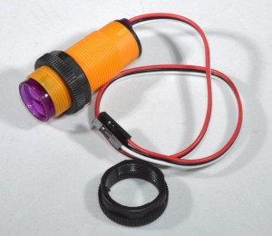
Check that each sensor has 2 mounting collars. Screw one onto the body of the sensor, leaving room at the front for the second one
ultpi_03

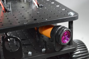
Push the sensor through from the rear of the mounting bracket and screw on the second collar. Feed the wires up through the holes in the top plate
ultpi_04

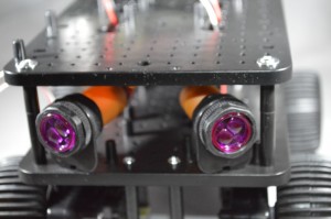
Repeat for the second side

step03

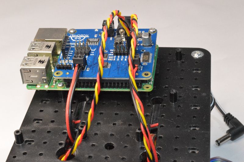
Connect to the RoboHAT INPUTs

  • Left sensor to Pin 7 (marked x07 or #04)
  • Right sensor to Pin 11 (marked x11 or #17)

The wire colours from the obstacle sensor are:

  • Black: Gnd
  • Red:  5V
  • White or Yellow: Signal

Make sure you connect them to the correct pins on the RoboHAT


3. Mounting the Line Sensors
ultpi_07

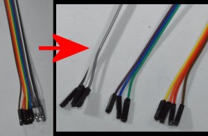
First, take the 30cm female-female jumper strip of 10 wires and split it into three strips:

  • Brown, Red, Orange, Yellow (this is for the Ultrasonic Sensor)
  • Green, Blue, Purple (this is for the Left Line Sensor)
  • Grey, White, Black (this is for the Right Line Sensor)
ultpi_08

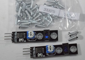
Next, prepare the two Line Sensors and 2 of the 3x8PB screws as shown
ultpi_09

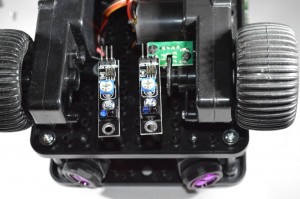
Screw the line sensors in position as shown, using the screwhole in the middle of the circuit board
ultpi_10

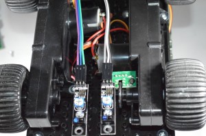
Connect the Green, Blue, Purple wire to the Left Sensor and the Grey, White, Black cable to the Right Sensor

** Note some sensors have the pins in order 5V, Signal, Gnd; other have them in order Signal, 5V, Gnd – make sure you know which wire colour is connected to which.
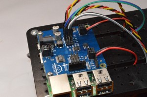
step04

Connect the sensors to the RoboHAT

  • Left sensor to Pin 29 (marked x29 or #05)
  • Right sensor to Pin 13 (marked x13 or #27)


4. Connecting the Pan/Tilt Assembly
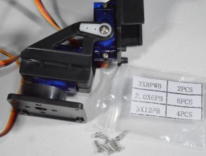
ultpi_12

This is now supplied fully assembled with the Initio Ultimate kit. If you have an unassembled one, then please visit the assembly instructions here (opens in new window)

Take 4 of the 2.0x6PB screws (these are the smallest ones in the packet and there are 6 of them)
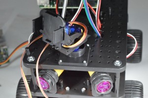
ultpi_13

Screw the base of the pan/tilt assembly to the upper plate in the position shown

Rotate the pan/tilt carefully left and right to access the screw holes
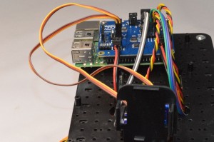
step05

Connect the Pan servo (bottom servo) to Pin 22 (marked x22 or #25)

Connect the Tilt servo (upper servo) to Pin 18 (marked x18 or #24)

Note the colours of the servo wires and ensure they are connected correctly:

  • Black: Gnd
  • Red: 5V
  • Orange or White: Signal


5. Connecting the Ultrasonic Sensor

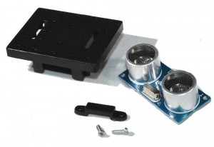
NOTE: More recent kits use a specially purchased ultrasonic sensor which has the connection pins at the front, instead of at the rear as shown below. If you have one of these, then simply use 2 small screws (included) to fit the sensor securely to the mounting plate. If your connection pins are at the back, please follow the instructions below. The wiring is the same in either case.
ultpi_15

For this you will need the mounting plate, saddle clamp and the final 2 of the 2.0x6PB screws used in step 4
ultpi_16

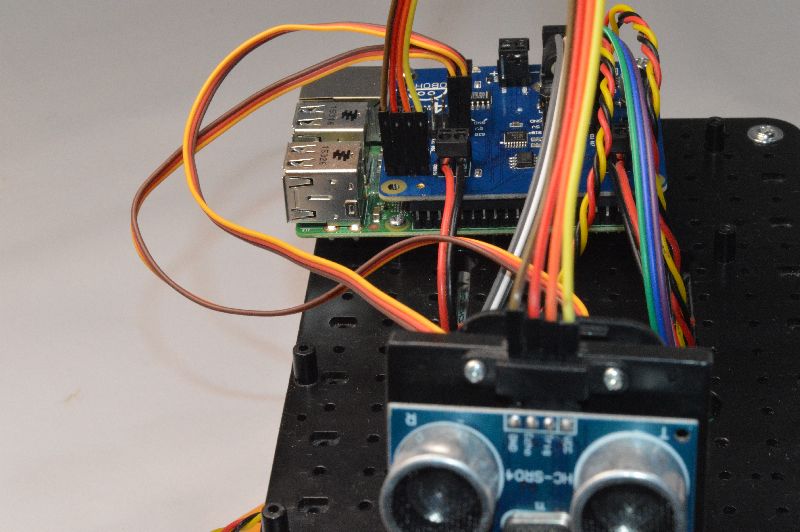
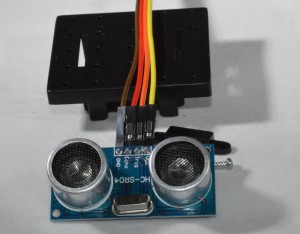
Push the 4-way 30cm female-female cable that you made in Step 3 onto the top of the ultrasonic sensor:

  • Brown: Gnd
  • Red: Echo
  • Orange: Trig or Ping
  • Yellow: 5V or VCC

ultpi_17

Screw the saddle clamp over the cable terminals as shown above
ultpi_18

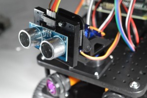
Clip the whole assembly to the front of the Pan/Tilt assembly as shown above

Note that you can purchase additional clip-on mounts so you could mount a camera on one and simply clip it off to change from Ultrasonic to Camera
step06

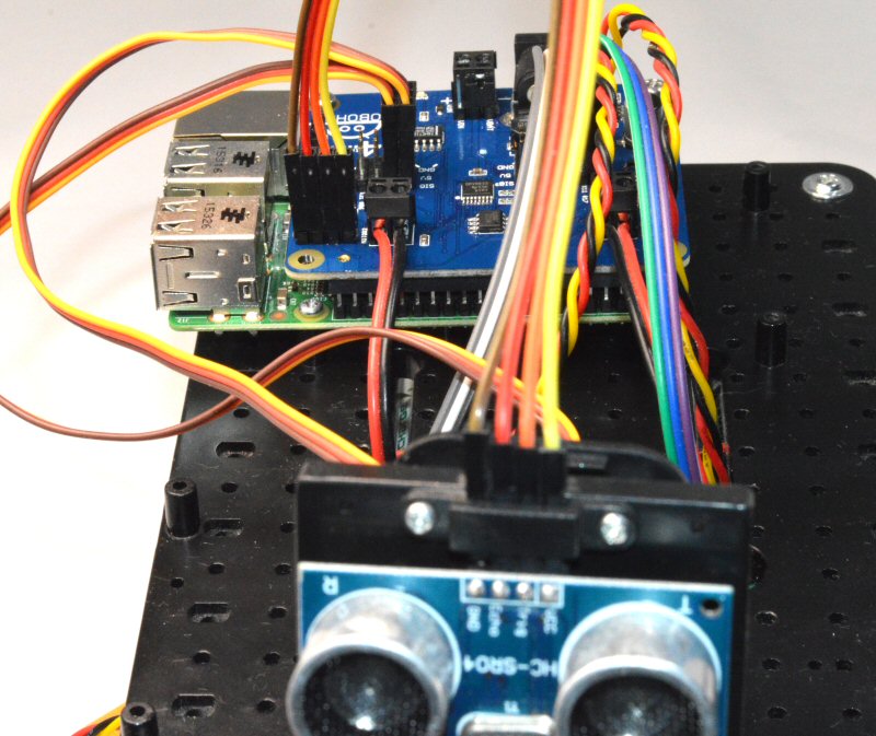
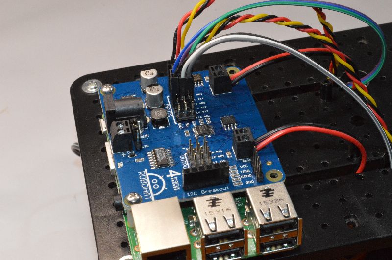
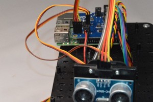
Connect the other end of the cable into the ultrasonic pins located between the 2 motor terminals

Ensure that Brown is Gnd, and they are in the order as shown


The main build of your Ultimate Initio Kit for the Raspberry Pi is now complete.


6. Connecting the Wheel Sensors (Optional)

Note that the wheel sensors require additional code to operate properly that is not included in the python library.

It is recommended that you do not fit these until you are familiar with the operation of the rest of the robot.

If you want to fit them, use Pins 15 and 16 (marked x15, x16 or #22, #23)

For each Wheel Sensor, connect:

  • Black to Gnd
  • Red to 5V
  • Orange or Brown to the selected pin (in fact, each wheel has 2 sensors that are slightly out of phase so you can get direction of travel from them, but you will then need 2 pins for each sensor)
  • DO NOT connect the sensor wires directly to GPIO pins on the Raspberry Pi as they are 5V signals. Always use beffered inputs as on the RoboHAT

It is recommended to leave the wheel sensor cables unconnected to start with

RoboHAT – Robotics Controller for Raspberry Pi

Links for Various Resources for the 4tronix RoboHAT

rh09


See the bottom of this page for software library and downloads.

 Useful Links

Know your RoboHAT

rh12a

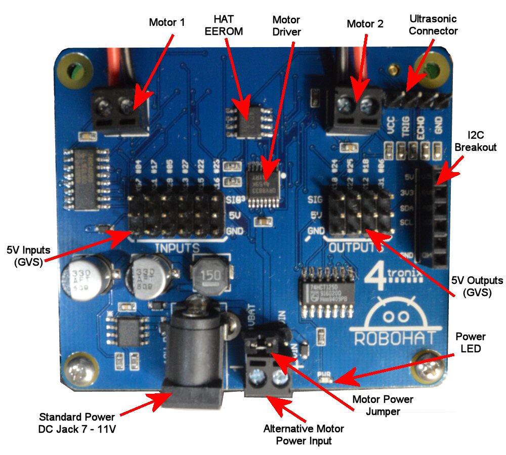
Clockwise from top left:

  • 2-way screw terminal for DC Motor 1 (left motor if using the Python library)
  • EEPROM containing the HAT information for the device tree
  • DRV8833 motor driver chip
  • 2-way screw terminal for DC Motor 2 (right motor)
  • 4-pin male connector for the Ultrasonic distance sensor (HC-SR04)
  • 6-pin female connector for the I2C breakout. This is the standard header used on all 4tronix controller boards
  • 4 x 3-way (GVS) inputs. These accept 3-5V input signals and are converted to the 3.3V logic required for the Raspberry Pi GPIO pins. They are labelled with both pin numbers and Broadcom GPIO numbers
  • Blue Power indicator LED
  • Jumper to select power input method for the motor driver. In most cases this should be to the left so that a single set of batteries can be used to power the Raspberry Pi and the motors. If you want a separate power supply for the motors, then move this jumper to the right and connect the separate motor power to the 2-pin screw terminal
  • 2-pin screw terminal for optional separate motor power
  • DC Jack for the main power input. This is the input from your (typically) 7.2V battery pack and is used to create the 5V for the Raspberry Pi and to drive the motors directly (if motor power jumper is to the left)
  • 6 x 3-way (GVS) outputs. These provide a 5V driven output from the Raspberry Pi GPIO pins. They are labelled with both pin numbers and Broadcom GPIO numbers


Pin Assignments

RoboHAT signals are mapped directly to individual GPIO pins as follows:

Description

In/Out

J5 Pin Number

Broadcom Number

1 Motor1 A

Out

36

16

2 Motor1 B

Out

35

19

3 Motor2 A

Out

33

13

4 Motor2 B

Out

32

12

5 Ultrasonic

In/Out

38

20

6 Input 0

In

7

4

7 Input 1

In

11

17

8 Input 2

In

29

5

9 Input 3

In

13

27

10 Input 4

In

15

22

11 Input 5

In

16

23

12 Output 0

Out

18

24

13 Output 1

Out

22

25

14 Output 2

Out

12

18

15 Output 3

Out

31

6


Python Software

To download the library and example programs from the internet, you can use the following commands from your Raspberry Pi in the home folder. (open LXTerminal from desktop):

  • wget http://4tronix.co.uk/robohat.sh -O robohat.sh
  • bash robohat.sh


Files included

  • robohat.py This is the python library module, see the first few lines of the library for listing of all the exposed functions for controlling motors, LEDs and reading sensors
  • motorTest.py – cycles through various motor directions
  • motorTest2.py – use the arrow keys on your keyboard to control the direction and speed of the motors
  • motorTestRaw.py – cycles through various motors, but doesn’t use the library
  • irTest.py – check the state of the IR line and obstacle sensors sensors (assumes you have the sensors connected as shown in the Initio build instructions)
  • sonarTest.py – prints the distance using the UltraSonic sensor
  • servo.py – a very simple servo test using the RPI.GPIO PWM commands
  • servoTest.py – a more sophisticated test that uses ServoBlaster (servod) to create the timing pulses

PZM – Pi Zero Motor Shim

Add Motors to (Almost) Any Pi Zero Project

2016-01-22_0008a

Purchase here

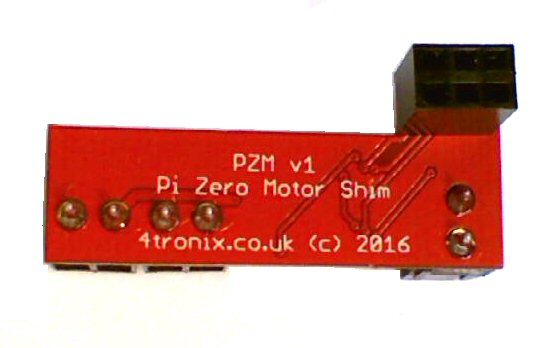
This tiny little board (38 x 16mm) can be added to a Raspberry Pi Zero (or any other Pi for that matter) to provide dual H-Bridge control of 2 DC motors.

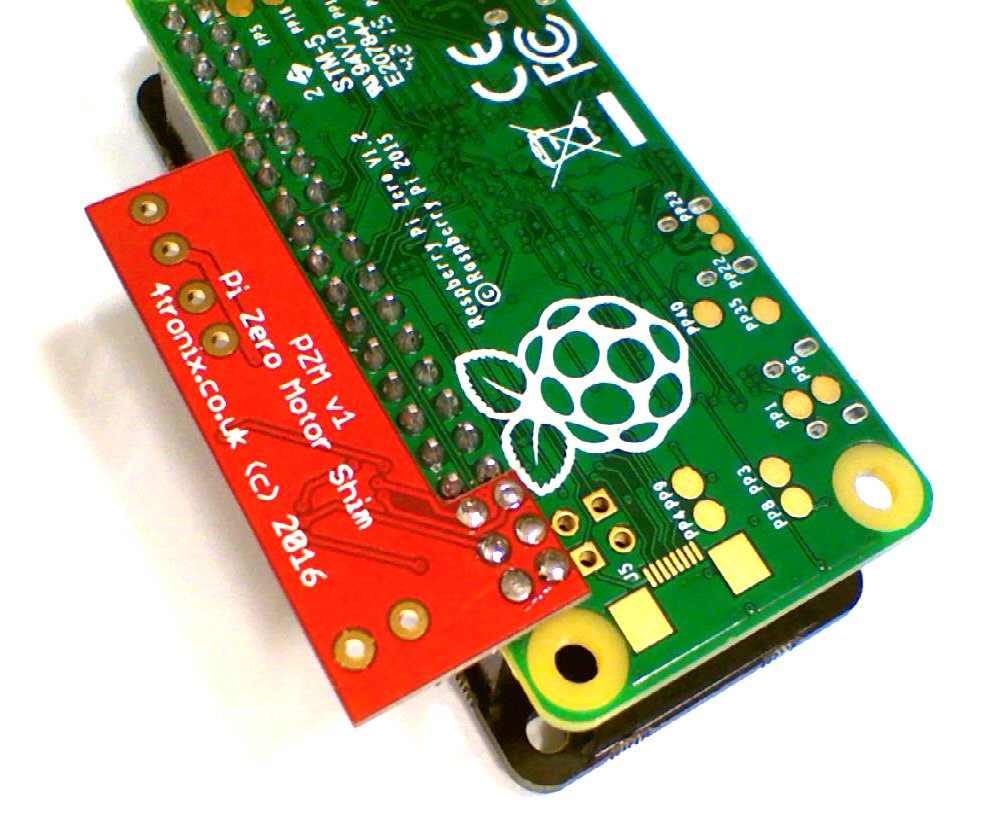
It is so thin (0.8mm) that it can be soldered onto the bottom of the connector (assuming you have added one to your Pi Zero), or you can solder on the female or male headers included in the kit so you can connect and remove it, however you have configured your Pi Zero.

2016-01-22_0007a

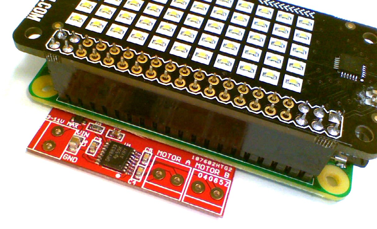
Above shows the PZM with a female header added so it can be plugged onto a “normal” male header as shown below, Note how the PZM sticks out from the Pi, so other boards can still be mounted as usual

2016-01-22_0002


Alternatively, you can mount it by soldering it directly to the bottom of the header, thus leaving the header free to attach other boards as shown below:

2016-01-22_0013a

2016-01-22_0012a


Contents

So what do you get in the package?

  • Ready assembled PZM shim
  • 3 x screw terminals
  • 3×2 Male header
  • 3×2 Female header

pzm_kit01


Programming?

This is a 4 pin driven, dual H Bridge. 2 pins control Motor A and 2 pins control Motor B

  • Motor A is physical pins 35 and 36 (Broadcom GPIO 16 and 19)
  • Motor B is physical pins 37 and 38 (Broadcom GPIO 26 and 20)
  • For each motor:
    • One pin High and the other Low for Forward
    • One pin Low and the other High for Reverse
    • Both pins Low will stop driving the motor and allow it to slowly coast to a halt
    • Both pins High will brake the motor and bring it to a halt very quickly
  • The pzm.py library module provides basic functions for forward, reverse, spin left, spin right, turn left/right forward, turn left/right reverse


Downloads:

From a terminal window on your Pi type the following lines exactly:
$ wget http://4tronix.co.uk/pzm.sh -O pzm.sh
$ bash pzm.sh

This will have created a pzm folder in your home directory, with the following files:

  • pzm.py python library
  • pzmTest01.py shows use of the motors without using the library
  • pzmTest02.py shows the motors moving in the same way as pzmTest01 but using the library (much simpler program)
  • pzmTest03.py allows the use of arrow keys (and , and . to change speed) to control the motor directions


Wiring?

  • Put power 3V to 11V on the terminal marked VIN and GND. If you are using low power motors you can use the 5V from the Pi (note this isn’t connected to the PZM board)
  • Reverse polarity protection is provided so you won’t break it by putting them on the wrong way round, but it won’t work until you get it right!
  • Connect one motor to Motor A and the other to Motor B
  • Done!


Gecko – The Friendly Flashy Codable Wearable Computer

Gecko: Have flashy, blinky fun while coding!

The new wearable, codable computer that is fully compatible with the Arduino UNO programming environment

Purchase from our shop here

Learn how to:

  • Flash LEDs
  • Change to all the colours of the rainbow (and more)
  • Listen for button presses and react how you want


What is Gecko?

  • Arduino UNO compatible processor
  • USB interface for power and programming
  • 12 independently programmable RGB LEDs (exactly the same to program as the popular neopixels)
  • 2 separate buttons for use in your programs
  • Delivered with demo sequences already prepared for your delectation and delight!


How do I Program it?

  1. First you will need to install the drivers for the Gecko (it uses a chip called CH340G). Windows7 and above (and Ubuntu 15+) will automatically install this driver but it will take a few minutes. Plug in the Gecko and wait for Windows to install it and let you know it is done
  2. Install the Arduino IDE from here
  3. Fire up the Arduino IDE and:
    1. Go to the menu Sketch/Include Library/Manage Libraries../
    2. Search for Fastled
    3. Click on the box and select Install
  4. Copy the simple LEDtest demo from here to your Arduino sketches folder and start editing it to do what you want


Here’s the simplest, but complete program to light an LED:

First we need to include the FastLED library that we installed:

#include “FastLED.h”

The we need must setup the data structure to store the individual LED values in. The line below creates an “array” of 12 elements, each of which has Red, Green and Blue numbers to define the separate brightness levels of each component of the pixel. Each value can be from 0 (completely OFF) to 255 (fully ON).

CRGB leds[12];

Arduino has 2 main functions that we need to use. The first is setup( ) which is run once at the start of the program. We set up all our initial values and things here.

The next line initialises the FastLED library to us WS2812B type LEDs connected to Arduino digital pin 13 and there are 12 LEDs in use. In the example programs the numbers 13 and 12 have been replaced by “constants” so that we can use them again and again without having to keep typing 12 for instance.

FastLED.addLeds<WS2812B,  13,  RGB>(leds, 12);

After running the setup( ) function, the Arduino runs the loop( ) function repeatedly. This is where you do all the programming to make the LEDs blink on and off, or chase each other, etc. Let’s simply blink LED 6 on with blue=100 and off . Notice below that after we have changed the array to turn LED6 on (or off), we call the FastLED function show( ) . This takes the data from the array and sends it to the LEDs.

leds [6] = CRGB (0, 0, 100);

FastLED.show( );

delay (1000);

leds [6] = 0;

FastLED.show( );

delay (1000);

That’s all we need for this simple test. Let’s see what it looks like in the IDE


Now we can press the Compile and download button in the Arduino IDE – shown in orange in the screenshot above.

If all goes well, the Gecko will start flashing LED6.

Another very useful FastLED function is setBrightness( ). You can use this to change the overall brightness level of the whole display. If you don’t use this function and set an LED to 255, 255, 255 (that is, bright White) then it will be extremely bright and potentially damaging to the eyes if you stare closely at it. If you call setBrightness(40), then setting an LED to 255, 255, 255 will actually only set it to 40, 40, 40. This is stil White and quite bright, but is less damaging and will use a lot less power – important if you are using a USB battery pack.


Using the Buttons

  • The buttons are on Analog pins:
    • A2 (Button A)
    • A1 (Button B)
  • In the setup( ) function you should enable the internal pullup resistors, otherwise they will always read LOW
    • pinMode(BUTTONA, INPUT_PULLUP);
  • When the button is pressed, you will receive a LOW from digitalRead(BUTTONA); otherwise a HIGH


Example Sketches:


Picobot 2

Overview

Picobot 2 is an all-new design, but recognisably similar to the original Picobot. Here are some of the key hardware differences:

  • Acrylic case for all models
  • Built-in LIPO battery and smart charger
  • USB interface for programming and charging
  • Supports Bluetooth Smart (Bluetooth Low Energy, BLE)
  • Supports Wifi using ESP8266 (NB. choice of Wifi or Bluetooth is a build-time option. One or the other, but not both)
  • Improved internal power supplies, keeps the ultrasonic sensor running even with low battery levels
  • Improved line follower and light sensors
  • Fully RoHS compliant


Links


Child-Friendly Assembly

It is *Really* simple to assemble the Picobot2. All you need is a small cross-head screwdriver and a few minutes.

pbstep01

Above shows all the parts that you receive in the box. Clockwise from top left:

  1. Picobot2 PCBA ready-assembled with motors
  2. LIPO battery (with protection circuitry)
  3. Wheels
  4. Screws and nuts
  5. Acrylic case (5 layers)

Visit this link to see the detailed assembly instructions


First Steps

When the Picobot2 is delivered, it contains 5 programs that you can access using the Mode button

1. Flashes the LEDs rapidly

2. Line Follower. Stick black insulation tape down and it should follow it (depends how reflective the surface it is on – fine on wooden floors!)

3. Light Follower. Follows a torch shining on it, but not very well at the moment

4. Obstacle avoider. When comes close to something, it reverses and turns around then moves off again

5. Person follower. Tries to stay at 10cm from an object. I need to slow down the movements as it is too jerky at present and goes off line.

The Mode button (right side, front) changes between these programs. When you press the button it will move onto the next one and flash the Blue LED the right number of times (ie. it will flash 3 times before running the light follower). The obstacle avoider program in particular doesn’t listen to the button very often, so you may have to hold it down for a couple of seconds before it reacts.


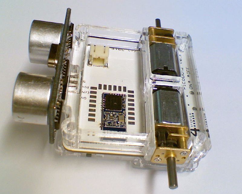
Know Your Picobot2

This image is from an earlier prototype, but gives the general picture – most of the electronics is on the underneath. The light sensors are on top at the front corners


Bluetooth Connection

The Bluetooth is a direct pass-through, with a small set of AT commands. So don’t start a packet with AT or it will be interpreted as a command. In the Arduino code you can open the software serial connection at 9600 baud, then read or write from it directly.

#include <SoftwareSerial.h>
SoftwareSerial BLE (2, 3); // RX, TX
  BLE.begin (9600);
BLE.println (“Hello world”);

 The AT commands are listed here

iOS (8 or later):  Use LightBlue app from the AppStore to find and listen or send data to the Picobot2: Tutorial

Android: Use the WIreless-Tag agg referred to in page 14 of the Bluetooth module specification here


ESP8266 Connection

There is an ESP-12E module used for WiFi and it is controlled via the Software Serial interface using AT commands.

With these AT commands you can connect to an existing WiFI network, create your own access point, or both. You can easily create a web server so that anyone with a WiFi enabled smartphone or PC can attach to your Picobot2 and control it, or simply receive updates about the sensors and what the Picobot2 is doing. It’s entirely up to you.
The AT commands are listed here


Latest Status

21st December: Released: Purchase here

  • Picobot2 is now released
  • Production capability is very limited at around 10 units per day, so if you order several there may be a delay before they are shipped
  • The second batch should be factory-produced and thus shipment in quantity will be possible
  • Once factory production is established, Picobot2 will be released to distributors


16th December: Released for pre-Order – Purchase here

  • PCBs have arrived as planned – Good News! They work 🙂
  • I thought when testing that there was a hardware problem, but after a lot of investigation, it turned out to be a problem with the new Arduino Picobot2 library code
  • This has delayed full testing, so there are things still to test such as Bluetooth, WiFI, voltage regulation, etc, but all is looking good so far
  • Now it is time to start planning the shipping roll-out. We’ve sold more than was expected so it is likely that later orders may not ship until the new year
  • We close for new orders on Monday 21st December, but will still ship outstanding paid for orders on 22nd December. After that we won’t be around
  • So if all goes to plan we will be able to ship the first order on 17th December. Other orders will follow in the order they were placed


13th December: Released for pre-Order – Purchase here

  • We now have the stencil which will enable solder pasting on the blank PCBs when they arrive
  • We also have the cases, with the 4tronix and Picobo2 logos etched into the top layer
  • PCBs have been manufactured and are on the way from China
  • PCBs expected on 16th December and should be tested and confirmed working the same day (cross all fingers, toes and any other appendages you have!)
  • So if all goes to plan we will be able to ship the first order on 17th December. Other orders will follow in the order they were placed

stencil

Metal foil solder stencil


case

New top layer with logo etching


3rd December: Released for pre-Order – Purchase here

  • For now, we have left off the new accelerometer because, to really be useful, it needs a lot more software support
  • Retail pricing (without Bluetooth or Wifi) is £36.00 + VAT
  • First production PCBs and cases have been ordered today
  • Arduino library code is being tidied up and documented fully
  • Still to do: Document use with Snap for Arduino and Blockly


19th November: The (hopefully) Final prototype PCBs due in today. To do:

  • Assemble and test the final prototypes
  • Decide which components to leave in or out (mainly, do we need the accelerometer?)
  • Work out final product cost and set distributor and retail pricing
  • Purchase the first small batch (100 units) of PCBs, cases and any other components we’re running short of
  • Keep working on software demos and libraries
  • Release for pre-order on our web-site


Assembling Picobot2

pb2_09

Assembling Picobot 2

Picobot2 has been designed to be easily assembled by children armed only with a small screwdriver. As long as you are gentle with the acrylic layers there should be no problems in assembly.

If you find an acrylic layer is not fitting properly then either you have the wrong layer, or (layer 2 only) it is upside down.

Click on any photo to enlarge.


Step 1 – Check you have all the parts

pbstep01

You should have (clockwise from top left):

  • Picobot mainboard with ultrasonic and motors attached. Optionally, you may have a Bluetooth module (shown above) or an ESP8266 WiFi module
  • LiPo battery (includes protection circuit and JST 2-pin 2mm connector)
  • 2 wheels (Yellow or Lilac)
  • 4 screws (M2.5, 22mm) and 4 nuts (M2.5)
  • Layer 5 (top) acrylic. 2mm thick
  • Layer 4 acrylic, 5mm
  • Layer 3 acrylic, 5mm
  • Layer 2 acrylic, 3mm (sits on component side of PCB)
  • Layer 1 acrylic, 3mm (Bottom – with front glider attached)


Step 2 – Place Layer 2 onto the PCB

pbstep02

Note that this layer only goes one way round as it weaves in and out of the components on the PCB.

This layer is quite fragile until it is assembled, do not bend it!


Step 3 – Place Layer 1 onto Layer 2

pbstep02

Layer contains the hemi-spherical glider, which acts as the front caster for the Picobot2


Step 4 – Turn over and Place Layer 3 Between the Motors

pbstep04

Layer 3 and Layer 4 are quite similar and both are 5mm thick. Layer 3 has a small cutout at the centre front where the ultrasonic module is mounted.


Step 5 – Add Layer 4 above Layer 3

pbstep05

This also fits between the motors and the top of this layer should be flush with the top of the motors


Step 5 – Plug in the Battery

pbstep06

Plug in the battery onto the main PCB then position it carefully into its cavity making sure that the antenna end (left side) of the Bluetooth or ESP8266 module is not covered by the battery


Step 6 – Add the Top Layer (Layer 5)

pbstep07

This top layer holds in the battery and the motors


Step 7 – Screw it all together

pbstep08

Do up all 4 screws. with the screw head at the top and the nut underneath the Picobot2. They don’t need to be done up very tightly, just tightening by hand is sufficient


Step 8 – Finally, push the wheel on

pbstep09

Put each wheel flat on the table and push the axle through the wheel until it is stopped by the table. The axle end should be flush with the outside of the wheel


You now have a fully functional (optionally WiFi or Bluetooth enabled) mini robot to program away with!

4tronix SD Card for Raspberry Pi

SD Card for Raspberry Pi


Latest revision: 30

Date: 31st December 2018

OS: pi@raspberrypi ~ $ uname -a
Linux raspberrypi 4.1.19-v7+ #858 SMP Tue Mar 15 15:56:00 GMT 2016 armv7l GNU/Linux

pi@raspberrypi ~ $ cat /etc/*-release
PRETTY_NAME=”Raspbian GNU/Linux 9 (stretch)”
NAME=”Raspbian GNU/Linux”
VERSION_ID=”9″
VERSION=”9 (stretch)”
ID=raspbian
ID_LIKE=debian
HOME_URL=”http://www.raspbian.org/”
SUPPORT_URL=”http://www.raspbian.org/RaspbianForums”
BUG_REPORT_URL=”http://www.raspbian.org/RaspbianBugs”


Installing the image on SD Card

  1. Download the compressed file from this link
  2. Uncompress the file using WinRAR or similar tool
  3. Requires 8GB or larger SD card
  4. For Windows, burn to the SD card using Win32DiskImager available from here
  5. For Mac, use ApplePi Baker from here


Revision History

4tronix-24 (18-MAY-16)

  • Fixed the issue with servod having incorrect permissions


4tronix-23 (26-APR-16)

  • NB: There is an issue with the servod program on this release – it is not set to executable and will give an error when running the scripts for Pirocon/Initio, RoboHat and Pi2Go. Fix this by typing:
    • chmod +x servod
  • Updated dist-upgrade (26/Apr/16)
  • Added ScratchGPIO support for RoboHAT


4tronix-22 (8-APR-16)

  • Updated dist-upgrade (8/Apr/16)
  • Supports Raspberry Pi 3 Model B Bluetooth and Wifi
  • File system expanded


4tronix-21 (19-MAR-16)

  • Updated to Jessie (18/Mar/16)
  • Supports Raspberry Pi 3 Model B
  • Added support for Picon Zero


4tronix-20 (29-FEB-16)

  • Updated to Jessie
  • Supports Raspberry Pi 3 Model B
  • Added support for RoboHat, PZM shim and Picocon
  • Removed password from VNC server


4tronix-10 (8-OCT-15)

  • Updated to latest Wheezy image
  • Updated with latest ScratchGPIO7 (fixes LEDs on Pi2Go and servos generally)
  • Updated servoblaster (servod) to work with new kernel
  • Split the Pi2Go and Pi2Go-Lite Scratch examples into separate folders and updated to use latest syntax