Using Cube:Bit with Raspberry Pi

Using Cube:Bit with Raspberry Pi

IMG_2288a

Attaching the Raspberry Pi

The Cube:Bit is a 3D array of neo-pixels (SK6812-3535 to be precise). As such it can be accessed like any other strip, ring or matrix of neopixels using WS2812B compaible code.

The base for the Cube:Bit (available separately) contains a 40-pin GPIO connector, into which a Raspberry Pi Zero can be connected directly. “Full size” raspberry Pis can be connected using a ribbon cable.

The 5V supply provided to the Cube:Bit base is also passed to the Raspberry Pi to power it, so no additional power is required.

Only BCM18 (physical pin 12) is used from the Raspberry Pi. This is the PWM pin that all neopixel code uses to communicate, so all existing code will work without changes.

Note: There is a power input selection jumper on the Cube:Bit base. Ensure the jumper is in the correct place for your power supply (usually USB or DC Jack)


Adding the Neopixel Driver to the SD Card

If you have already used neopixels on your Raspberry Pi with the SD card you are using, then you don’t need to do anything here. Your existing code will work, although you would get strange shapes due to the layout of the individual LEDs in the Cube:Bit.

If you haven’t already installed the driver then there are a number of ways to do it. I find the easiest and reliable way is to run Pimoroni’s curl script from here: https://github.com/pimoroni/unicorn-hat Ensure your Raspberry Pi is connected to the internet and then type:

\curl -sS https://get.pimoroni.com/unicornhat | bash

You do not need to install the unicorn hat examples (although having a Unicorn Hat and using the examples is an excellent idea!)

This has now added the rpi_ws281x driver for neopixels. This driver is used by the Cube:Bit library


Adding the Cube:Bit Library and Examples

The cubebit.py library module is a layer over the rpi_ws281x driver library that implements functions specific to the Cube:Bit, such as mapping x, y, z co-ordinates to specific pixels, writing to defined planes, etc.

Although not strictly necessary (you could write your code to talk directly to the rpi_ws281x driver), it does allow code from the Microbit using the Makecode package to be easily ported to Raspberry Pi as many of the same library calls are implemented in the same or similar ways.

Again, with your Raspberry Pi connected to the internet, run the following commands to download the cubebit.py library and example code

wget http://4tronix.co.uk/cb.sh

bash cb.sh

This has now created a cubebit folder on your Raspberry Pi which contains the cubebit.py library and a number of example programs.

NB. For all these examples you should change the variable side to be the number of pixels per side on your Cube (eg. 3, 4, 5 or 8). This is always set near the top of the program. side = 5

You will need sudo access to run these, so for example: sudo python purpleRain.py

Type Ctrl-C to exit these demos.

  • test.py shows a rainbow on all pixels for 50 seconds, then starts stepping through each x,y,z value with a single yellow-ish pixel
  • purpleRain.py shows a cloud of purple pixels on the top layer, then flashes white (lightning), then the raindrops fall randomly and collect in a pool at the bottom. Finally, the “water” is recycled via one edge back to the top
  • planeTest.py moves a plane of randomly coloured pixels through the Cube:Bit in each direction repeatedly


Talon Grabber Assembly & Use

Talon Grabber for BitBot, BitBot XL and Robobit Buggy

IMG_2245a


Purchase Talon here


Assembling Talon for BitBot and BitBot XL

Images show the Classic BitBot version. The BitBot XL version is identical except for the shape of the PCB.

Step 1 – Ensure you have all the parts

IMG_2225a

Your kit should contain:

  • 3 x PCBs: Talon Base, Talon A, Talon B
  • 10 x Screws: M2.5, 6mm
  • 2 x Screws: self-tapping 6mm (there are also longer ones in the servo bag – ignore these)
  • 1 x Screw to attach servo arm to the servo (this is in the servo bag)
  • 1 x Metal gear servo (with various servo arms and screws
  • 1 x M3, 12mm, male-female pillar
  • 1 x M3, 6mm screw
  • 1 x M3 nylock nut
  • 1 x Pimoroni spanner widget to help tighten nylock nut
  • 4 x M2.5, 12mm pillars to attach to Bit:Bot


Step 2: Attach the Pillar for Floating Jaw

Step2

You will require the Talon Base PCB, M3 screw and M3 pillar

Fit the screw through the side of the board shown above and screw tightly into the female end of the pillar. Ensure this is firmly attached


Step 3: Fit the Servo to the Talon Base

Step3a

You will need the servo and 2 of the M2.5, 6mm screws

Step3b

Ensure the servo is positioned on the opposite side of the PCB to the pillar, and the shaft of the servo is in line with the pillar.

Pass the screws through the holes in the PCB and tighten into the flanges of the servo

Step3c

Turn the PCB over and take the servo wire

Step3d

Wrap it around the servo twice then plug the end into the 3-pin connector. Brown wire to the pin labelled GND, Red to VCC and Orange to P15


Step 4: Fit the Floating Jaw

Step4a

You will require Talon B and the M3 nylock nut.

Fit the Talon B board onto the pillar so the the Talon logo is facing towards the talon Base PCB

Then screw on the nylock nut all the way, then undo it about quarter of a turn until the Talon B jaw can move freely without wobbling up and down

Step4b


Step 5: Fit the Servo Arm to the Driven Jaw

Step5a

You will need Talon A, the straight servo arm (from the servo bag) and the 2 small self-tapping screws (not the longer ones in the servo bag)

DO NOT pass the large shaft on the servo arm through the PCB. This shaft needs to be facing away from the PCB.

Step5b

The screws then pass through the PCB into the Servo Arm and should be tightened.

Step5c

Do NOT fit this arm to the Talon assembly yet. We need to get the servo working from the Bit:Bot first


Step 6: Fit the Talon Assembly to the Bit:Bot

Step6a

You will need the 4 M2.5, 12mm pillars and 4 of the M2.5 6mm screws

Screw from the bottom of the Bit:Bot into each pillar, and tighten well. The pillars should be point upwards

Step6b

Then using 4 more of the M2.5, 6mm screws, attach the Talon assembly to the top of the pillars.

Step6c

Note that the servo should be at the top and the floating jaw at the bottom

Step6d


Step 7: Fit the Driven Jaw (Talon A)

Step7a

You will need the small screw in the servo bag to attach the drive jaw to the servo.

But first: Set the servo to position 5 degrees. If using the Makecode Bit:Bot package, then use the open talon block:


Once the servo is in the correct position, then fit the Talon A jaw, making sure it is closed and is interlocking with the floating jaw (Talon B)

Step7b

Screw the little screw into the servo shaft to hold it in place


All done! Now you can open and close the jaws by setting the claw/talon to different values between 0 (fully closed) and 90 (fully open)

Cube:Bit – Magical RGB Cubes

Cube:Bit

Magical RGB “neo-pixel” Cubes of awesome

IMG_2188a

Purchase Cube:Bit here

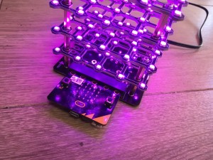
The Cube:Bit collection is a range of 3D “neo-pixel” compatible cubes that are easily built from individual 2D slices.

The current range consists of 3×3, 4×4 and 5×5 slices together with a base unit that allows power to be added easily (big cubes can use a lot of power), and also allows a Micro:Bit or Raspberry Pi Zero to be plugged in directly. Of course you can use the Cube:Bits without the base and with any microcontroller thats supports neopixels: Arduino, Raspberry Pi, even Crumble (although the Crumble only supports up to 32 pixels at present, so only the 3x3x3 Cube:Bit can be controller)

Assembling the cube is easy with threaded rods in each corner providing the structural strength as well as the electrical connections.

Programming it is equally simple as these just appear as a string of neopixels, so use your favourite neopixel driver for your controller.

For the BBC Micro:Bit we have developed a MakeCode package that allows you to use the Cube:Bits extremely simply as well as giving you full x,y,z control of each pixel.

Cubebit_Package01

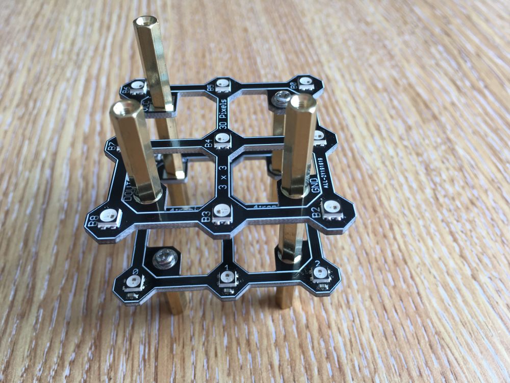
Assembling a Cube:Bit

The basic construction method is:

  1. Place the 1st slice A-Side up
  2. Place second slice B-Side up, ensuring Vcc/5V and Gnd are in correct place
  3. Place third slice A-Side up
  4. Continue placing slices as required, alternating A-Side and B-Side
  5. Each Slice has a DOUT (Data Out) from the lower slice connected to its own DIN (Data In) connection. This means that there is a “free-hanging” female-female pillar which is alternately on the left and then on the right, with a matching gap in the vertical pillars on the opposite side
  6. You can stack these as high as you want – no need to limit yourself to a simple Cube – but watch the power requirements!

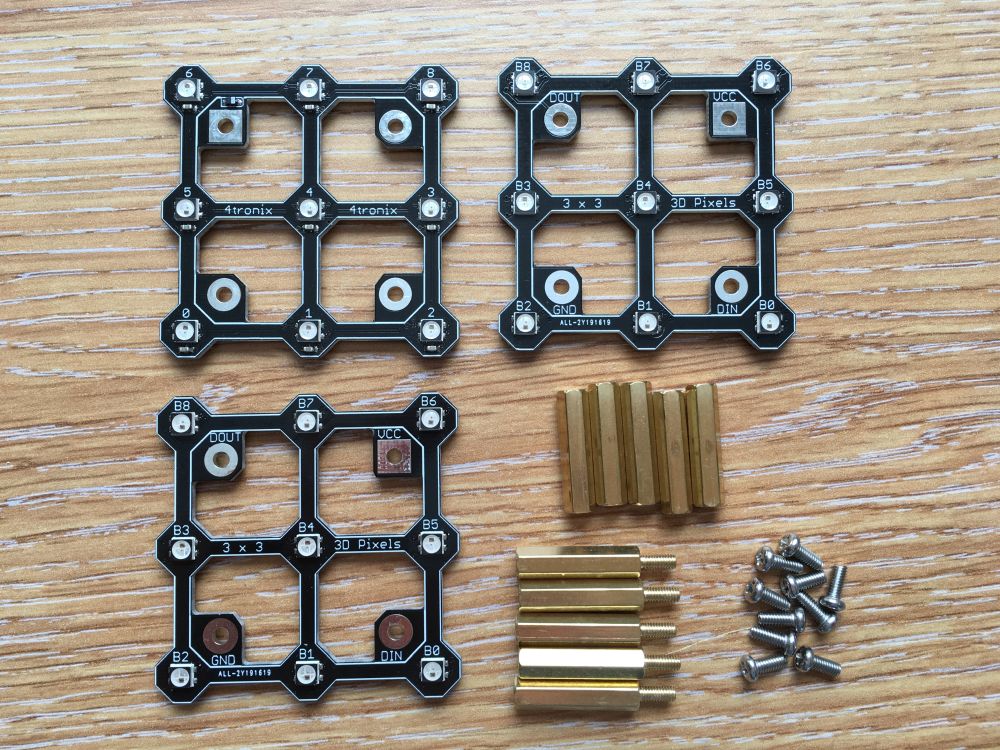
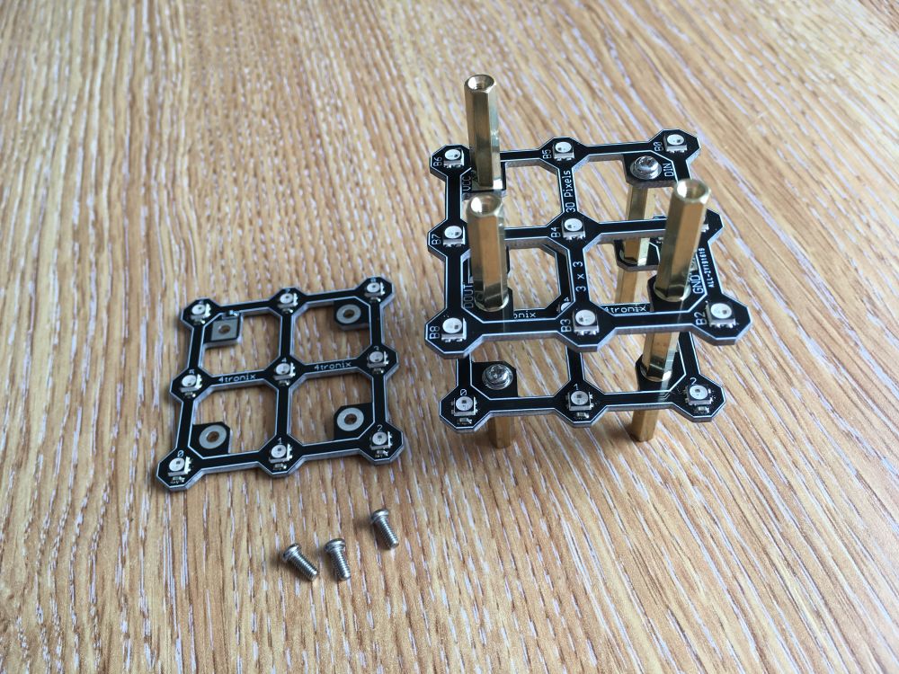
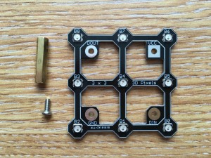
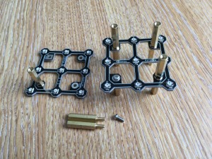
Step 1 – Check you have all the bits

IMG_2198a

3x3x3 – 3 slices, 5 female-female pillars, 5 male-female pillars, 10 screws

4x4x4 – 4 slices, 6 female-female pillars, 7 male-female pillars, 12 screws

5x5x5 – 5 slices, 7 female-female pillars, 9 male-female pillars, 14 screws

The construction method is the same for all Cube:Bit sizes. Just keep going upwards as you add more slices

IMG_2199a

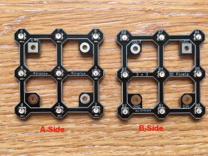
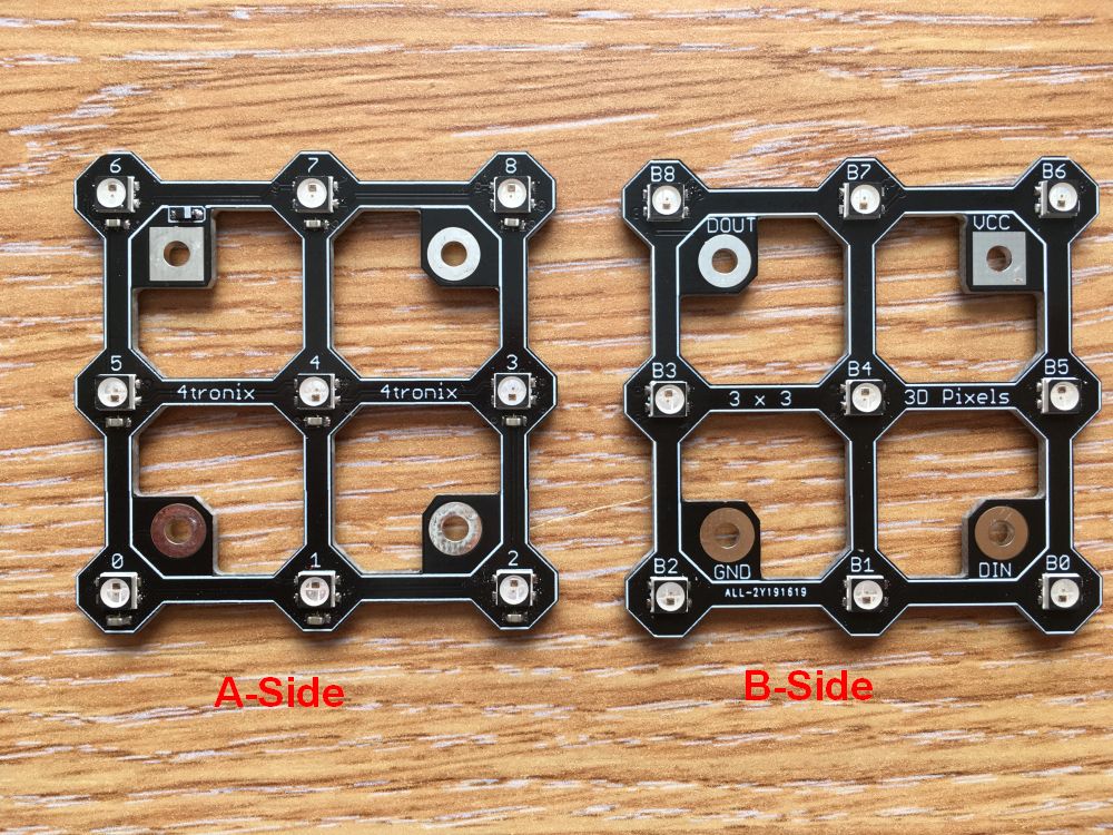
Make sure you can tell which is Side A and which is Side B for each slice (These are more clearly labelled on release version):

  • Side A has the names for each LED as 0, 1 , 2, 3, etc.
  • Side B has the names as B0, B1, B2, etc.

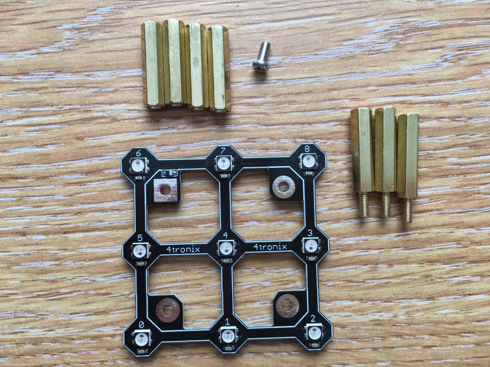
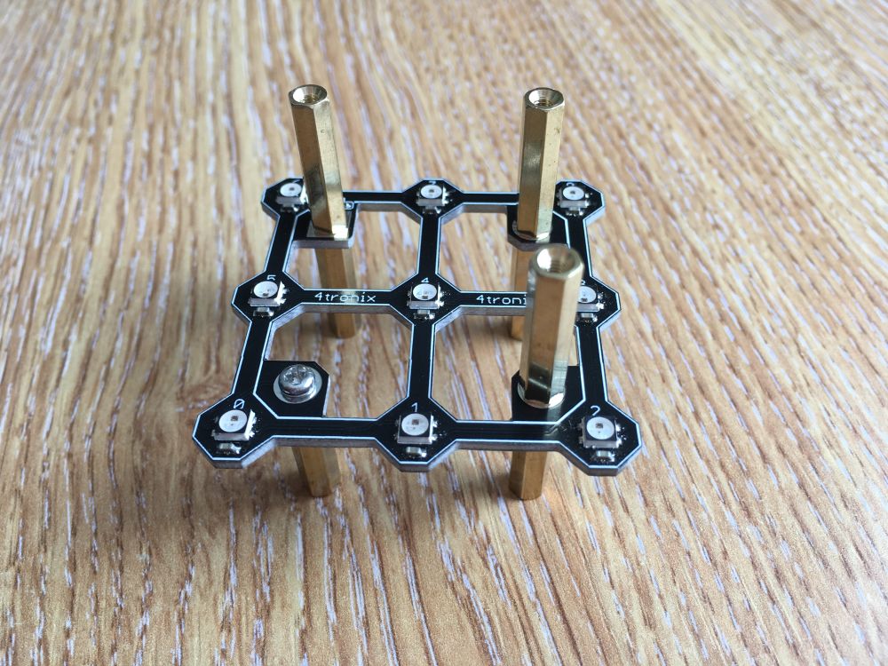
Step 2 – Add Pillars to bottom slice

IMG_2200a

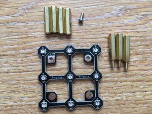
You will need 4 female-female pillars for underneath, and 3 male-female pillars and a screw for the top

Make sure you have the slice with the A-Side upwards, then fit a female-female pillar below the DIN connection (next to LED 0) using the screw

IMG_2201a

Fit the other 3 female-female pillars using the male-female pillars to hold them in place

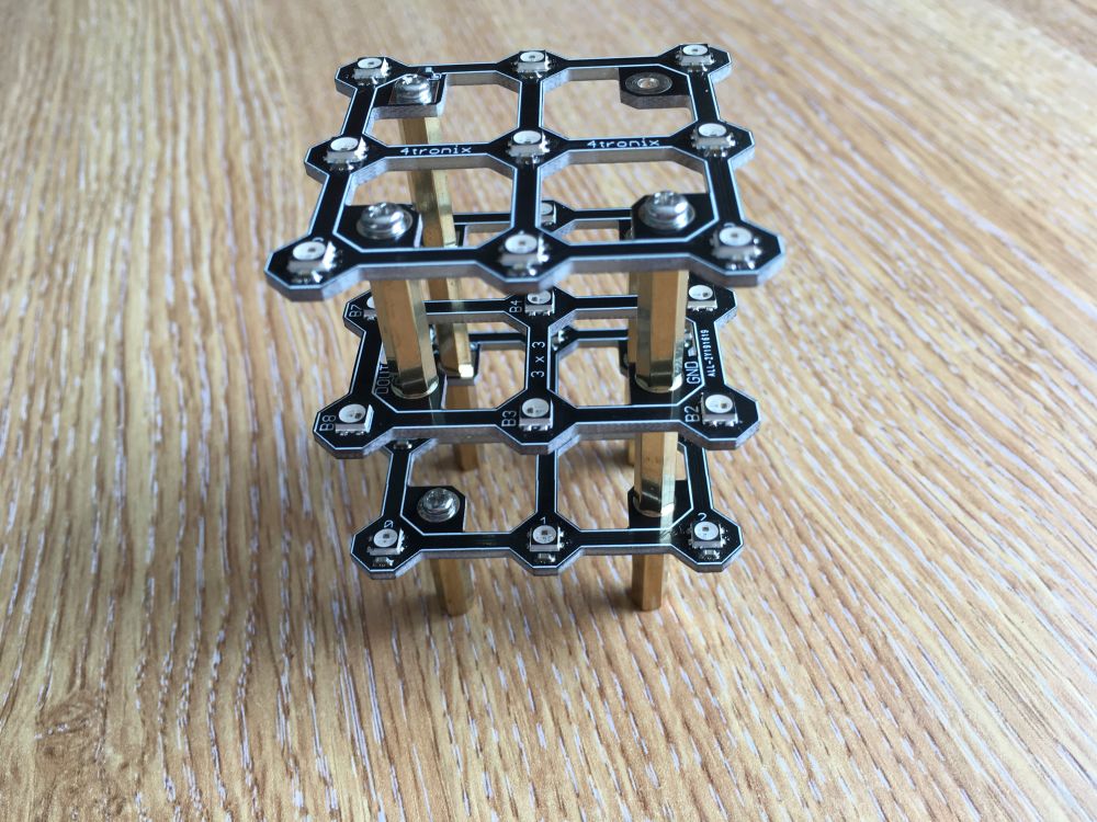
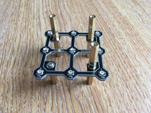
Step 3 – Prepare the Second Slice

IMG_2202a

Make sure the slice is B-Side upwards, then take a female-female pillar and a screw and fit the pillar on top of the slice in the DOUT connection (next to B8, B15, or B24 depending on your cube size)

IMG_2203a

Step 4 – Fit the Prepared Second Slice

IMG_2204a

Use 2 male-female pillars and a screw.

IMPORTANT: Make sure you place Vcc/5V on this slice directly above Vcc/5V on the slice below.

Screw the pillar from the DOUT of the lower slice into DIN of this slice using the screw

Then use the male-female pillars to attach the remaining 2 pillars from below

IMG_2205a

Now repeat steps 3 and 4 as often as required, remembering to alternate A-Sides and B-Sides as you stack the slices

IMG_2279a

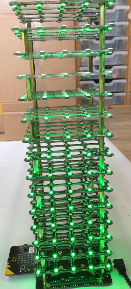
In fact you can keep going as high as you like to make a tall tower – this one is 5 x 5 x 15 slices high

TIP: If you are using the Makecode extension, then there is a block called “set height of tower” that you should use before the “create cube:bit” block

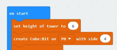
Access this block from the …more category within the Cubebit extensions

Step 5 – Fit the Top Slice

IMG_2206a

Back to A-Side upwards (assuming 3x3x3 or 5x5x5).

Use three screws to fit the top slice, ensuring that it is DOUT that is NOT connected and that Vcc of this slice is still above Vcc of previous slice

IMG_2207a

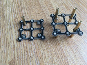
You now have the completed cube on legs as well as spare screws/pillars.

Final options at this point are:

  1. Leave as is and use croc clips (alligator clips) to connect to the legs for 5V, Ground and Signal
  2. Connect to the base using 4 of the spare screws. Make sure you connect 5V and Vcc
  3. Remove the bottom legs and change the first pillars to female-female held in with screws. This makes a tidy cube, then connect to it using soldered wires or tags, etc.

Powering Your Cube:Bit

These cubes have a lot of LEDs and LEDs require power. The 3x3x3 has 54 LEDs and the 5x5x5 has 250 LEDs. On full brightness with White colour this will be several amps.

You _can_ drive them with a low current as long as you set the brightness down low (40 or less) and you don’t set a lot of LEDs to white. This is perhaps suitable for the 3x3x3 cube.

I recommend however using the base and supplying power either via the USB connection or the DC jack connection. There are other connectors on the base as well. Make sure you have changed the jumper to select the power input you are using!

Example currents used (powered by 5V)

  • 3x3x3 all LEDs at Red, brightness 40 (out of 255) – Current 150mA
  • 3x3x3 all LEDs at White, brightness 40 – Current 340mA
  • 3x3x3 all LEDs at White, brightness 255 – Current 1.9A
  • 4x4x4 all LEDs at Red, brightness 40 – Current 350mA
  • 4x4x4 all LEDs at White, brightness 40 – Current 800mA
  • 4x4x4 all LEDs at White, brightness 255 – Current 4.5A
  • 5x5x5 all LEDs at Red, brightness 40 – Current 680mA
  • 5x5x5 all LEDs at White, brightness 40 – Current 1.6A
  • 5x5x5 all LEDs at White, brightness 255 – Current 8.75A

These numbers are important. For instance on the microbit you shouldn’t power the LEDs directly.

So use a 2.5A power supply for the 3x3x3 cube, 5A for 4x4x4 and 10A for the 5x5x5. Although if you set the brightness down low etc. then using lower current power supply is possible and we do most of our testing using a 4A supply. If the brightness is set to 40 (the default) then you can use a 3x3x3 cube with 0.5A power supply and a 4x4x4 with 1A.

Connections:

  • Signal from controller (eg Micro:Bit) to DIN on the bottom slice
  • Ground from controller to GND on bottom slice
  • Ground from power supply to GND on bottom slice
  • Power from 5V DC power supply to Vcc/5V on bottom slice

IMG_2208a

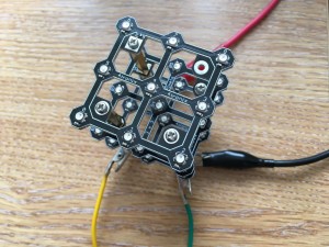
Photo above shows using croc clips to connect to the legs. Yellow is signal from Micro:Bit Pin 0, Green is Gnd from Micro:Bit. Black is Gnd from power supply and Red is power from power supply

IMG_2209a

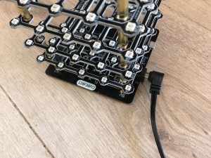
In the photo above we’re using a 5V DC power supply with a 2.1mm DC Jack connector (centre positive) that connects directly onto the base. The signal and ground from your controller of your choice then connect elsewhere on the base (eg. the croc clip connection or the GVS connector or the 4tronix Playground connector)

Using Cube:Bit with Raspberry Pi

Please follow this blog entry for installation, Cube:Bit python library and examples.

MakeCode for Micro:Bit Extension

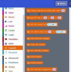
There is a Makecode extension that makes it easy to use the Cube:Bit using x,y,z three-dimensional matrix address of the pixels.

The slice is physically laid out with the LEDs snaking from the DIN corner then back along the next row, and so on until it reaches the DOUT corner (ie. along x axis then along y axis). As alternate slices are mounted upside down and rotated, then the snaking goes along y-axis then along x-axis in these slices. So it is much easier to use the built-in mapping block.

To load the package (until it is formally released) go to Advanced (or click on cog icon) then select Extensions. In the search box add the URL https://github.com/4tronix/cubebit

This provides the following blocks:

Your first block in the start of program should create a cube of the correct size. If you are using the Cube:Bit base then this will connect via Pin0, but you can change this when not using the base. This will create a string of neopixels of the correct length for your cube and set the brightness to the default of 40. If you want, you can change the brightness with the “set Cube:Bit brightness” block, anywhere from 0 to 255 (255 is the brightest)

You can then write a colour to any or all of the pixels in the cube. eg set (x,y,z) 2,3,0 to Blue when Button A is pressed

Note that this is using the map block to convert x,y,z co-ordinates to a Pixel ID

Note also that the show Cube:Bit changes block is required to actually set the LEDs to the new values that you have set.

TIP: Setting LEDs is always a two part process. Make all the changes you want then show the changes on the Cube:Bit. Just making the changes has no effect on the pixels as it only changes internal memory. This is the FIRST thing you should check if your program is not creating the effect you require

There is a block that allows you to write to a whole plane of pixels at one time. Decide which axis the plane lies on and which plane within that axis:

Additionally you can specify exactly which RGB values to use, instead of simply picking one of the predefined colours:

Make a Rainbow

An easy and fun way to start is to create a rainbow effect using the built-in blocks

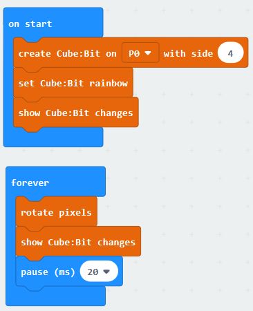
The Start block creates the cube then sets the LEDs to a rainbow scheme (the show cube:bit changes block makes the LEDs match the settings you have selected

Then the Forever block moves the colours all the pixels by one position. Taking the colour of the last pixel and putting it back into the first pixel. This is called rotation. It does this every 20ms so you get an ever-changing colour effect

Example Software

While testing Cube:Bit we have developed a few interesting animations and games for CubeBit

You can download them all from this zip file

Extract the files into a folder on your PC (and remember where you put them)

Then click on Projects, then Import File, then browse to find the file you require.

All examples have a variable called “side” which is set at beginning of the Start block to be 3, 4 or 5 depending which size Cube:Bit you have. Changing the value of side will allow the rest of the program to work correctly and of course affects the way the x, y, z mapping is calculated. You will need to change this line so that it sets the correct size for your Cube:Bit.

  • PlaneBounce – this simply lights up a plane and moves it left and right. Coloured Green going right and Red going left
  • raindrop – sets a blue/white colour to be rain on the top of the Cube, then drops each pixel to the bottom one at a time and randomly. If you tilt the cube, different planes become the top (at the start of each cycle)
  • PurpleRain – as raindrop, but in purple and with a lightning flash at the start and rain recovery animation at the end
  • RainSplash – as raindrop, but makes a little splash as each raindrop lands (not great!)
  • Revolver – rotates planes in random axis and colours. This works best with larger cubes
  • RGBTest – cycles through Red, Green, Blue and White, lighting every pixel on the Cube. A good test of power supply – check the White is actually White and not a yellow/orange colour
  • Scan – lights up all LEDs in x, y, z order from 0, 0, 0 to size of the Cube
  • TimesCube – builds a small 2x2x2 cube in one corner and grows it to fill the Cube:Bit, then shrinks into a different corner. And repeat
  • TicTacToe amd BitCommander – provides a 2 player game of 3D Noughts and Crosses. Install the BitCommander software on the microbit in your Bit:Commander and the TicTacToe software in your Cube:Bit. Use the buttons and dial on the Bit:Commander to move your person around and press on the Joystick to select the pixel you want. The cursor then changes from Red to Green and it is Player 2’s turn. When a line of 3 is made in any direction, the winning line is flashed on and off. Press the Red button on Bit:Commander to start again

Basic Building Blocks

Basic Building Blocks

IMG_1570a

Basic Building Blocks is a range of soldering kits to make Raspberry Pi add-on boards (aka HATs). The 40-pin GPIO connector is already soldered on all boards (including when you purchase “board only” instead of the complete kit). So you typically only have to add a few components and headers by hand.

Because the boards are very basic, you are not forced down one way of operating. Also, all the boards are sold as bare boards (with GPIO header already fitted) or as a complete kit

In addition, by using an extended female header and appropriate mounting pillars, you can stack these boards together allowing multiple functions simultaneously. Many of the boards have the ability to use different pins for each function by changing jumpers or solder jumpers around.

Purchase Basic Building Blocks here

Download the sample software here


DC Motor

IMG_1556aIMG_1553a

Click on any photo to enlarge

This can be purchased as a Quad motor kit or a Dual motor kit. The Quad motor kit comes with two L293D motor drivers, whereas the dual comes with just one.

Make sure you are adept at soldering. There are plenty of good soldering videos on the web and other resources to get you going.

Solder this kit by fitting the lowest height components first: Diode, then capacitors, then IC sockets, then 2-pin screw terminals.

  1. Ensure the diode is the correct way round. White band to the left as shown in the photo above
  2. Capacitors can go either way round
  3. IC sockets should be placed with the notch to the left to match the position of the silk screen on the board (nearest the words IC1 and IC2 as appropriate). If you only have one L293D (ie. the Dual version) then you can choose which position to use
  4. The 2 screw terminals for each pair of motors should be clipped together before connecting to the board. Slide the right hand one down the side of the left one and ensure that it forms a smooth joint all round.
  5. Cut all the pins neatly underneath using side-cutters, not forgetting the screw terminals which could foul on the HDMI header of the Pi if left long
  6. Insert the L293D driver chips with the notch on the chip matching the notch on the socket

Now you’re ready to go. Plug it carefully onto your Pi and use whatever language you want to control it.

The default pins are:

  • Motor 1: 04, 18
  • Motor 2: 17, 27
  • Motor 3: 19, 20
  • Motor 4: 21, 26

These are set by default in the pin selection area. To change them you will need to cut the small track on each solder jumper above the holes labelled 1A, 1B, 2A, 2B etc. Then wire in your choice of pins from the long row of holes above to the 4 holes on each side

Programming motors is easy using GPIO.ZERO


Bit:Commander Games Consoler & Controller

Bit:Commander for BBC micro:bit

IMG_1812a

The Bit:Commander is a great device for powering and experimenting with the BBC micro:bit.

Purchase Bit:Commander here


Makecode Extension for Bit:Commander

In Makecode, go to Advanced and select Add Package. Then search for BitCommander and add the extension

Overview

As well as a battery pack (3 x AA batteries required), the Bit:Commander includes

  • Edge Connector for easy connection of the BBC micro:bit
  • Robust on/off switch
  • Blue power indicator
  • 6 multi-colour RGB LEDs (aka neopixels)
  • 4 square 12mm push buttons with coloured caps (Red. Yellow, Green, Blue)
  • Analog dial input with centre click detent for easy centreing
  • Analog Joystick with X and Y movement and a push switch
  • Powered miniature speaker


Suggested uses:

  • Acting as a remote control for another micro:bit device, such as a Bit:Bot
  • Acting as a self-contained portable (no wires) games console
  • Experimenting with various Digital and Analog inputs available as well as the speaker and neopixel outputs
  • Everything is pre-fitted. No wires, soldering or jumpoers to fiddle with


Pin Connections:

  • Speaker: Pin 0 (*)
  • Dial: Pin 0 (*)
  • Joystick X: Pin 1
  • Joystick Y: Pin 2
  • Joystick button: Pin 8
  • Neopixels: Pin 13
  • Red Button: Pin 12
  • Yellow Button: Pin 16
  • Green Button: Pin 14
  • Blue Button: Pin 15

(*) Pin 0 is used both for Speaker output (using the Music or Tone output methods) as well as the Dial analog input. This causes some compromises – most notable of which is that the Dial analog input cannot reach its normal maximum value of 1023 and stops at around 850 instead. As long as the software understands this, then it shouldn’t be a problem.

NB. The Bit:Commander is only powered if batteries are fitted and it is switched on. Powering the micro:bit does not power the Bit:Commander. However, when the Bit:Commander is powered up, then it will also power the micro:bit


Resources:

Music:Box with Blinkie Plugins

Music:Box with Blinkie Plugins

IMG_1701a

The music box is a small board that makes your BBC micro:bit totally mobile with blinky LED plugins and on-board powered speaker

Purchase here

Specification:

  • 3xAAA battery holder
  • Robust on/off switch
  • Blue indicator LED
  • Mini speaker with powered driver
  • Fittings for BBC micro:bit (version from v1.0 onwards have edge connector instead of pillars and screws. No functional change to the operation however)
  • Connector for neopixel plugins

Making Music

The powered speaker is connected to Pin 0 of the Micro:Bit. This is the default pin for the music modules in micropython and Makecode

So in Makecode, you could simply create this block to run once at the start. From the “Advanced melody” section of the Music group, select the “Play” block:

In micropython, you can do the same thing with the following code:

from microbit import *
import music
music.play(music.ENTERTAINER)

You can make your own music or use one of the built-in tunes. You can also play the tune in the background, so you can be doing other things while the music is playing. To play forever in the background:

with Makecode

with micropython

from microbit import *
import music
music.play(music.ENTERTAINER, wait=False, loop=True)

More micropython help can be found here

Flashing the Neopixels

At the front of the Music Box there are 2 rows of 4 pins, with symbols next to them indicating “facing forward” and “facing backwards”. The outer 2 pins of each 4 are power and ground and the inner two pins are Data in and data out.

The row of pins nearest the edge of the board (facing outward) are the first neopixels in the chain. The data out from these, goes to the data in of the 4 pins facing into the board. This means you can put one plugin facing outwards and one facing inwards. The plugin facing inwards would start at LED10 (assuming a standard 10 neopixel plugin is in the first position).

If you only have an inward facing plugin, you must link the data in and data out of the outward facing pins. This is why there is a little back jumper included. If you only have a plugin facing outward, then you don’t need the little jumper, but you can keep it safe by plugging it into the inward facing pins.

Phew!

On the Music:Box the neopixels are connected to the MicroBit pin 1, so remember to select Pin 1 in the following code examples

Plug your selected plugin (Santa, Snowman or Christmas tree for now) into the 4 pins nearest the edge of the board. the LED marked 0 at the bottom is the first LED in the chain of neopixels.

Now you can use the standard neopixel modules in your selected MicroBit language.

For Makecode, you can do this to set all the pixels to Red when the A button is pressed

NB: The neopixels are on Pin 1 and they use GRB format (as shown in the example above)

Don’t forget to include the ‘show’ block after you have changed the pixel colours. It doesn’t actually update the pixels themselves until you do. You will also find that the LEDs will light up even if the Music:Box is not switched on. However, the colours won’t be correct and it will generally be quite dim. Always switch on the Music:Box when testing LEDs.

For micropython, you can do something like this:

from microbit import *
import neopixel
np = neopixel.NeoPixel(pin1, 10)
np[0] = (50,60,100) # set R,G,B values of pixel 0
np.show()

Again, you must run the show method after setting pixel values and ensure that the Music;Box is turned on. More micropython help can be found here

Examples

  • MusicBox.py This micropython program randomly flashes the neopixels and plays your choice of tune when A button is pressed. Stops when B button is pressed. You can hear glitches in the music when the neopixels are being update
  • NoteSynch.py  this micropython works in a similar way to MusicBox.py, but it plays each note individually and then updates the neopixels. This synchronises the music with the light show and also removes the glitches in the music

4duino – Arduino Uno Compatible Products

4duino – Arduino Uno Compatible Products

Range01a

Purchase 4duino here

4tronix have created a range of Arduino compatible boards with our own brand of magic.

All members of this new range are fully compatible with Arduino Uno software, and the 2 larger Uno form factor boards are fully hardware compatible as well

In addition, the 4duino range features:

  • 16MHz ATMega328P-AU processors
  • 14 Digital I/O pins (5 of which can be PWM – Pulse Width Modulated)
  • 8 Analog input pins (6 of which can be Digital I/O as well)
  • Built-in 5V regulators (check individual specifications for current ratings)
  • Reset buttons
  • Full USB interface (using CH340 interface chip)
  • Micro-USB connector

The 4duino Uno full-size products also have:

  • DC Jack for powering via up to 11V
  • Coloured coded pins (Pro) or available holes for 3-pin sensors (GVS – Ground, Volts, Signal) for all 22 I/O pins

Schematics

You can download the schematics for these boards from the following links

Programming 4duino Boards

As these boards are fully compatible with the standard Arduino Uno, you should follow the instructions and reference examples at www.arduino.cc to download programming software, libraries, example files and lots of tutorials.

The additional motor drivers on the Pro versions of these boards you will need the pin information and a brief example:

  • Motor A Pins: D5 and D9
  • Motor B Pins: D6 and D10

The motor driver is a standard dual H-Bridge (DRV8833 chip):

  • Setting one pin High and the other Low will drive the motor one direction
  • Swapping High and Low will drive the motor in the opposite direction
  • Setting both to Low, or both to High will stop the motor
  • (setting both High will brake the motor quickly, setting both Low will allow the motor to coast to a stop)
  • The following code, drives one motor forwards, then backwards, then stops:

// the setup routine runs once when you press reset:
void setup() {
// initialize the digital pins we will use as an output.
pinMode(D5, OUTPUT);
pinMode(D9, OUTPUT);
}

// the loop routine runs over and over again forever:
void loop() {
// Forwards, then wait 500ms
digitalWrite(D5, HIGH);
digitalWrite(D9, LOW);
delay(500);
// Reverse, then wait 500ms
digitalWrite(D5, LOW);
digitalWrite(D9, HIGH);
delay(500);
// Stop, then wait 500ms
digitalWrite(D5, LOW);
digitalWrite(D9, LOW);
delay(500);
}

Powering the Boards

The 4Duino range can be powered by putting between 7 and 10V into the DC Jack connector (not available on the Mini or Mini Pro). It can also be powered with 5V on the USB connector – eg. connecting directly to a PC. Finally it can be powered by putting 5V onto the 5V signal.

Powering the Motors

The motors use a separate power supply from the Arduino processor. This is because the 5V regulators cannot deliver as much current as you may need to use, but this depends on the motors used.

4Duino Pro: You can select using jumper J3 whether the motor power is taken from the DC Jack input or the separate 2-pin screw terminal. The full voltage on the selected input is used to drive the motor. Note that the Ground signal is common to the Arduino chip, the DC Jack input and the 2-pin terminal.

4Duino Mini Pro: The power for the motors is taken from the end pin labelled ‘+’. For low power motors this “could be” connected directly to the 5V pin on the board, but probably best to connect to the Vin pin.

Download the CH340 Drivers for your OS

4duino Uno

IMG_1548d

This is software and hardware compatible with an Arduino Uno. You can use all the same addon Shields and get the same performance. In addition, we have made the extra 2 Analog pins available via the holes on the board into which you can solder headers if required.

These extra analog pins can be used within the Arduino IDE as A6 and A7. Note that they are analog ONLY – there is no ability to do a digital read or write on them and there is no ability to set pullup resistors.

Currently, the 4duino Uno is a depopulated 4duino Uno Pro board – so you can upgrade it to the full Pro specification with some surface mount soldering! Adding the GVS headers is much easier and a great upgrade though.

The USB interface is via the CH340 chip which has drivers available for all operating systems here.

On board 5V regulator: 1A


4duino Uno Pro

IMG_1548c

This is the fully populated version of the board that includes an integrated 2-channel H-bridge motor driver (the DRV8833).

The 4duino Uno Pro is fully hardware and software compatible with an Arduino Uno. You can use all the same addon Shields and get the same performance. In addition we have added colour-coded GVS headers for all the I/O pins including the additional 2 analog pins, A6 and A7. Note that these additional analog pins are analog ONLY – there is no ability to do a digital read or write on them and there is no ability to set pullup resistors.

The great news is that the Pro version also includes a 2-channel full H-bridge motor driver so you can control motors without requiring any addition shields or messy wiring. In fact, with the GVS headers installed, together with the motor drivers, the 4duino Uno Pro is like combing an Uno, sensor shield and motor shield into a single board!

On board 5V regulator: 1A

Motor control Pins:

  • Motor 0:  D5, D9
  • Motor 1:  D6, D10


4duino Mini

IMG_1571a

The 4duino Mini is an extremely small version of the Arduino Uno with all the same I/O pins, USB interface, reset button and voltage regulator.

All 22 I/O pins are brought out to the board edge where you can connect directly to them or solder in the provided headers.

The extra 2 analog pins can be used within the Arduino IDE as A6 and A7. Note that they are analog ONLY – there is no ability to do a digital read or write on them and there is no ability to set pullup resistors.

It is intended that headers, if fitted, are fitted so that the underside of the board is visible during use. This side of the board has no components and so has more room for labelling of all the pins.

Certain pins have symbols around them:

  • Circle: this is a digital pin that is capable of PWM
  • Octagon:  These are the Ground connections
  • Square:  One of these is 5V and is either a 5V input to the board, or a 5V output if you are using the onboard 5V regulator. The other square is the VIN for the voltage regulator. This can be from 6V to 9V. So if you are using this board with 4xAA batteries you would have a 6V nominal voltage which you apply to the VIN and GND inputs. You can then use the 5V pin to power the rest of your ciruit (up to 150mA)

On board 5V voltage regulator:  150mA

  • Dimensions: 33.75 x 18.5 x 1mm
  • Weight: 2g


4duino Mini Pro

IMG_1678a

The 4duino Mini Pro is a slightly longer version of the 4duino Mini. The extra length is used to house the dual H-Bridge motor driver and associated components, as well as the motor power input and motor power outputs. The remainder of the board is identical to the 4duino Mini

All 22 I/O pins are brought out to the board edge where you can connect directly to them or solder in the provided headers.

The extra 2 analog pins can be used within the Arduino IDE as A6 and A7. Note that they are analog ONLY – there is no ability to do a digital read or write on them and there is no ability to set pullup resistors.

It is intended that headers, if fitted, are fitted so that the underside of the board is visible during use. This side of the board has no components and so has more room for labelling of all the pins.

Certain pins have symbols around them:

  • Circle: this is a digital pin that is capable of PWM
  • Octagon:  These are the Ground connections
  • Square:  One of these is 5V and is either a 5V input to the board, or a 5V output if you are using the onboard 5V regulator. The other square is the VIN for the voltage regulator. This can be from 6V to 9V. So if you are using this board with 4xAA batteries you would have a 6V nominal voltage which you apply to the VIN and GND inputs. You can then use the 5V pin to power the rest of your ciruit (up to 150mA)

On board 5V voltage regulator:  500mA (peak)

  • Dimensions: 43.75 x 18.5 x 1mm
  • Weight: 2.6g

Motor control Pins:

  • Motor 2:  D5, D9 (labelled on PCB as M2, but is M0 to be consistent with 4duino Uno Pro)
  • Motor 1:  D6, D10
  • The + and – pins on the opposite side from the Motor pins are what is used to power the motors. You need to wire these to your board power input or raw 5V or whatever if you need to power the motors.


CrumbleBot Mk2 and XL

CrumbleBot 2 and CrumbleBot XL – Assembling and Coding

crumbot2_02

Purchase CrumbleBot Mk2 here


CrumbleBot Mk1

If you are looking for information on the previous versions, please check the older blog entry here


Updated Features

  • 8 Addressable RGB LEDs (‘Sparkles’)
  • Easy to use buzzer
  • 2 push button switches
  • Jumpers with handles, instead of crocodile/alligator clips
  • “Wire-free”, low-profile battery holder (no USB connectors or wires to get broken)
  • Modified motor mounting positions to reduce dust ingress into the gearbox
  • Improved, smooth-running, front caster
  • Powered front accessory connector


Assembling CrumbleBot Mk2 and XL

Click any photo to enlarge

Step 1 – Check you have the correct Parts

Step00

You should have the following items in the box:

  • CrumbleBot Mk2 or XL main circuit board
  • 2 x Wheels
  • Battery Holder PCB
  • 10 x small 7mm pillars to mount Crumble (not required for version 2.1 or XL as pillars are pre-fitted)
  • 2 x larger 12mm pillars to mount battery holder
  • Caster ball and housing (Mk2 only – prefitted on XL)
  • 2 x M2, 6mm screws to attach caster (Mk2 only)
  • 2 x M2 nuts for caster (Mk2 Only)
  • 10 x 4mm M3 screws (v2.0 has 20 x 5mm) to attach Crumble
  • 4 x 8mm countersink head screws to fit battery holder
  • 4 x Yellow (colour may vary) jumpers with “handle” to select function of each connection
  • 4 x coloured 12cm jumper leads for when the little yellow jumpers can’t reach


Step 2 – Fit the Caster (Mk2 only)

Step01


Step02

Use the 2 small M2, 6mm screws to pass through the caster underneath the CrumbleBot and fit the nuts on the top of the CrumbleBot mainboard.

Caster is pre-fitted on CrumbleBot XL


Step 3 – Fit the Crumble mounting Pillars (v2.0 Only)

Step03

NB. V2.1 and XL Has these pillars ready-fitted – skip this step

V2.0: Use 10 of the small 5mm screws to fit the 10 small pillars on the top of the CrumbleBot.


Step 4 – Fit the Crumble

Step04

Use the 10 M3, 4mm (for v2.0 use the remaining 10 small 5mm) screws to attach the Crumble to the 10 pillars fitted in Step 3.


Step 5 – Fit the Battery Holder Pillars

Step05

Use the 8mm screws to fit the 2 longer 11mm pillars into the holes marked “GND” and “PWR”


Step 6 – Fit the Battery Holder

Step06

User the remaining 2 longer 8mm screws to fit the battery holder to the 11mm pillars.

NB. Ensure  the switch and LED are at the rear of the robot


Step 7 – Add the batteries and Jumpers

Step07

A good starting point for the jumpers is in the middle two positions on the left side, and the outer two positions on the right side.  This allows use of the line sensors, sparkles and buzzer without changing anything.

CrumbleBot XL has an extra position on the left side. This to enable the ultrasonic sensor and connect it to I/O pin A


Step 8 Optional – Add the Ultrasonic Distance Sensor

IMG_1368a

Using the four 6mm screws, screw the two 20mm (11mm on XL)  pillars into the front accessory connectors. Then screw the sensor module onto the top of the the two pillars as shown above.

For Mk2, to connect the sensor to the Crumble, you must use one of the 12cm jumper wires to connect to a GPIO pin. On XL use the yello jumper in its most forward position

All our examples use GPIO A so wire it as shown in the photo above. (Mk2 only, remember to remove the Yellow jumper attached to GPIO A). Now you can use the distance block in the Crumble software, setting both T (Trigger) and E (Echo) to the same pin. A in this case.


Your CrumbleBot Mk2 or XL is Finished and ready for Coding!


Coding Your CrumbleBot

 1. Understanding the Jumpers

The Crumble has 4 general purpose IO (GPIO) connections, labelled A, B, C, D. These are all interchangeable for everything except driving Sparkles, which can only be done using GPIO D.

CrumbleBot Mk2 brings each GPIO connection to 2 positions on a jumper block and the XL adds another position for I/O pin A. The other side of each position is connected to one of the functions of the CrumbleBot. Thus, you can use the little Yellow jumpers to connect from a GPIO to one of the functions on the CrumbleBot2. For instance the top row on the left-side connector block is connected to to GPIO A (on the right of the connector block) and to the left side Light sensor (on the left of the connector block). Fitting a Yellow jumper across the top row will therefore connect the light sensor to GPIO A. If instead you connect the yellow jumper to the next row down, you would be connecting GPIO A to the line sensor. (As an aside, it is possible to connect each GPIO to 2 different signals at the same time – this won’t damage anything but will give unexpected results).

So the default settings for the yellow jumpers will connect the GPIO as follows:

  • A to the left Line sensor
  • B to the Buzzer
  • C to the right Line sensor
  • D to the 8 on-board sparkles


2. Driving the Motors

The Crumble has its own motor drivers which are connected directly to the motors on the CrumbleBot. You do not need to make any special connections to make these work. Each Motor is driven independently and you can select the speed (0 to 100) and direction (Forward or Reverse) in your code.

To drive the CrumbleBot2 forward, you would set each motor to the same speed Forward:

And to drive the CrumbleBot in reverse, you could set each motor to the same speed Reverse:

If both motors are going the same speed, but opposite directions, then the CrumbleBot2 will turn on the spot:

If the motors are turning different speeds, then the CrumbleBot2 will drive in an arc


3. Flashing the LEDs

The LEDs on the CrumbleBot2 are called “Sparkles” in Crumble-speak. You can easily code them to flash different colours using the colour-picker, or by setting different Red-Green-Blue (RGB) values.

First of all, make sure that GPIO D is connected via a jumper to  “LEDs” – this is the default setting of the yellow jumpers.

This bit of code continuously makes all the LEDs flash Green on and off:

Of course, you can set each Sparkle to different colours and brightnesses – they do not have to be all the same. The following code implements a “Larson Scanner” famous from the KITT car in the Knight Rider show. It’s a bit complicated, but bear with it.


4. Following a Line

The CrumbleBot2 has built-in, digital, line following sensors. Make sure that the jumpers are set to connect GPIO A to the left line sensor and GPIO C to the right line sensor. This is the default setting. The following code drives forward until one of the sensors detects a line, then it turns toward the line until the line is not detected any more. This is a very inefficient “way to do it” (algorithm). Can you find a better algorithm for following lines?

You should make the black line out of something that doesn’t reflect light, with the background being a good reflector. Black electrical tape is good and so is printing black lines on a laser printer – here is a good resource for printing line-following tracks.


5. Making a Buzz

The CrumbleBot2 contains a little buzzer (small, round and black, underneath the battery holder). This buzzes loudly (quieter if the sticker is left on the top!) when the input is set to Hi.

The default jumper settings have the buzzer connected to GPIO B, so the following code makes an annoying beep every second:


6. Acting on Switches

There are 2 switches on CrumbleBot2 SW1 (A) on the left side and SW2 (B) on the right side. You will need to move the jumpers from their default positions to use them. The following code modifies the buzzer code in 5. “Making a Buzz” so that it waits for SW1 (A) to go HI (pressed) then starts the buzzer until SW2 (B) is pressed. You will have to use a 12cm jumper wire to connect GPIO A to the SW1 (A) – not forgetting to remove the yellow jumper. So this should have:

  • 12cm Jumper wire from GPIO A to SW1 (A)
  • Yellow Jumper from GPIO B to BUZZ
  • Yellow Jumper from GPIO D to SW1 (B)


7. Following the Light

CrumbleBot2 has 2 light sensitive transistors which produce an analog value from 0 (very dark) to 255 (very bright).

We can use a similar program to the line follower. What we want to do is turn the robot to the side that has the most light. Because the light sensors can vary a lot, we must be careful that we don’t turn the robot every time there is a very slight difference in light levels, otherwise it would spend all its time turning and never move forward much. So we create a guard band in the software and make sure the light levels are sufficiently different before we decide to turn the robot. This is why we compare the X and Y variables and make sure there is a difference of at least 10, before turning.

Connect the yellow jumpers for GPIO A and GPIO C to Light


8. Use the Distance Sensor to Follow You around

Using the optional ultrasonic distance sensor, we can make the CrumbleBot2 follow us and stay the same distance away. The following code measures the distance to an object (eg. your feet). If it is too far away then the CrumbleBot2 moves Forward. If it is too close, then it moves in Reverse. This is a simple way to make a robot “friend”

Bit:2:Pi Control Raspberry Pi Addon Boards with your Micro:Bit

Bit:2:Pi Control Raspberry Pi Addon Boards with your Micro:Bit

IMG_1053a

[Click on any image to enlarge]

Purchase >HERE<

Overview

Bit:2:Pi (Pronounced Bit – to – Pie) is a connector and power management system that allows you to plug in a Micro:Bit at one end and a Raspberry Pi addon board (26-pin or 40-pin, HAT, pHAT or other) at the other end.

In between there are some breakout and connection headers that enable you to customise how the two boards are connected.

The power on the board is managed so that:

  1. Any or all power sources can be connected safely at the same time
  2. The Micro:Bit is never used to power the Raspberry Pi HAT (this is true for Bit:2:Pi v1.0 or later)
  3. Power for the HAT is provided either by the micro-USB connector at the HAT end, or by an attached battery holder
  4. The On/Off power switch controls the power to the HAT as well as to the Micro:Bit
  5. The “5V” signal on the HAT connector is actually from the battery or the micro-USB. If using the battery, this is likely to be around 4.5 to 4.8V using alkaline batteries, or 3.6 to 4.0V using rechargeable batteries. Not all HATs will work at these voltages.

To control the Raspberry Pi addon board (shortened to “HAT” from now on), you must write some code for the BBC Micro:Bit:

  • Many HATs are simply setting GPIO pins High or Low and for these you can use any available language easily. Simply set the Micro:Bit pin corresponding to the HAT GPIO pin (as determined by the various jumpers)
  • Some HATs use neopixels (eg. PlayHAT or Unicorn HAT). These require the neopixels to be driven by GPIO18 (physical Pin 12). By default, this is Pin 2 on the Micro:Bit
  • Some HATs require I2C commands (eg. Picon Zero). You can use the standard I2C commands within Micro:Bit to send and receive the necessary data. The default configuration connects the I2C pins
  • Some HATs require SPI connections (eg. various Analog boards using the MCP3008 or similar). Again the SPI pins are connected by default


Configuration

The male header block closest to the Micro:Bit (labelled MBit/RPi in v1.0) is where most of the configuration is done.

The MBit side of the header is labelled with the Micro:Bit pin numbers and the RPi side of the jumper is numbered with the GPIO names (Broadcom names)

The Bit:2:Pi is supplied with 13 little black jumpers that connect across from the MBit side to the RPi side. This gives the default settings as follow:

Micro:Bit Pin

GPIO Pin

Physical Pin

0

04

7

1

17

11

2

18

12

8

27

13

12

22

15

16

23

16

5

24

18

11

25

22

13

SCL

5

14

MISO

21

15

MOSI

19

19

SCLK

23

20

SDA

3

If you need to connect something differently, then simply remove the appropriate black jumper(s) and use a short Female-Female dupont wire to connect theMicro:Bit pin(s) to the appropriate Raspberry Pi pins.


Example Boards

[this section requires tested boards with example code – contributions welcome]

Some tested working boards are:


External Contributors

Several people have written some software for the Micro:Bit to work with Raspberry Pi addon boards using the Bit:2:Pi adaptor. Many thanks go out to these contributors!


Michael Rimicans (Twitter @heeedt)


Neil Avery (Twitter @veryalien)


Les Pounder (Twitter @biglesp)


 Mark Atkinson (www.multiwingspan.co.uk)