Pi2Go Progress Update – August 4th 2014

Pi2Go Progress Update (4/8/14)

cf01

As people keep pointing out to me, it’s been a while since I gave an update on Pi2Go progress. This is not because nothing has happened, but actually because so much has been happening that I haven’t sat back and reflected on the work we’ve done. Some highlights:

  • Manufacturer in China has been selected and cost of product from them has been agreed
  • The first “production” sample has been produced – made using final components, but hand-soldered
  • A “Pi2Go-Lite” has been defined, tested and is ready for kitting
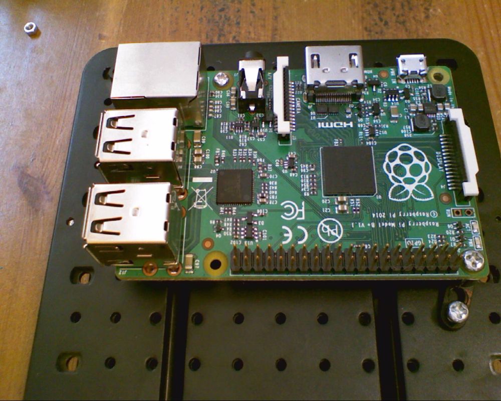
  • The Raspberry Pi Model B+ caused a redesign of the main PCBs – as the mounting holes and other components are crucial to the design
  • A python library has been developed that senses which version of the Pi2Go is in use and acts accordingly
  • Extremely effective switching regulator used on both boards – keeps the Pi and wifi connection up even with very low battery levels
  • A pan/tilt mechanism has been developed for attaching a Pi camera
  • New Pi2Go logo created and Pi2Go is shortly to become a registered trademark
  • Selling price for the first production run has been decided

Pi2Go_800

Specifications


Pi2Go

Pi2Go-Lite

Main PCBA dimensions (mm)

110 x 80

100 x 80

PCBA Colour

Red

Yellow

Component technology

Surface Mount

Through Hole

Assembly method

Fully soldered

Requires Soldering

Supports Model A, B and B+

Yes

Yes

Power Supply

6 x AA

6 x AA

5V Regulator

3A Switching

3A Switching

Battery Monitoring

Yes*

Light sensors

4 x analog

RGB LEDs

4 pairs, hardware PWM

White LEDs

2 front, 2 rear (paired, s/w PWM)

Ultrasonic sensor

Yes

Yes

Line sensors x 2

Yes

Yes

IR obstacle sensors

3 with anti-glare technology**

2

Wheels

65mm Black

65mm Yellow

Servo connections

4 (Hardware PWM)

2 (Software PWM)

I2C Breakout connector

Yes

Yes

LED indicators for IR sensors

Yes

Yes

Geared motors ratio

120:1

120:1

Motor connection

Plug & Socket

Screw terminal

Power connection

Plug & Socket

Screw terminal

Time to Build (approx/varies)

20 minutes

90 minutes***

RRP (ex VAT)

£59.95

£35.95

Notes:

*  Battery monitoring circuit continuously checks that the battery levels is sufficient to power the motors and the Raspberry Pi. If it starts getting low, then it disables the motors. If it gets even lower then a signal is sent to the Raspberry Pi which can be used to shut down the Pi gracefully. This function can be over-ridden by changing a jumper

** “Anti-glare technology” prevents false triggers in bright sunlight. However the sunlight can still swamp the IR system which can prevent any events being received

***  90 minutes is estimated based on 1 hour to solder the PCBs and 30 minutes to assemble. Depending on soldering speed and ability, this can vary widely. “Your mileage may vary”
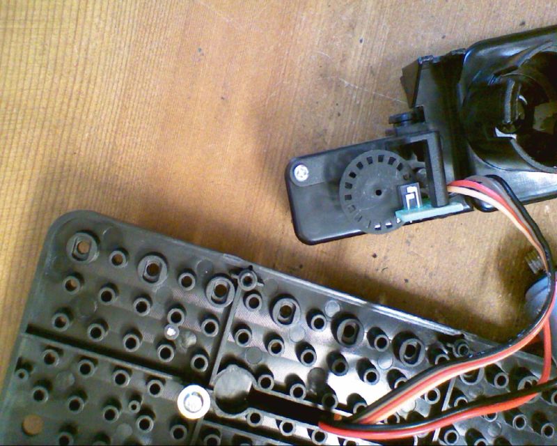
 

Pan/Tilt Assembly

The same design is used for both Pi2Go and Pi2Go-Lite. Continuing the theme of using PCB material (FR4) as a construction method, we’ve created 4 separate elements that can be used in different combinations:

  1. Base mounting plate. This can be fixed directly to either version of the Pi2Go using extended pillars on the front mountings. The base mounting plate can:
    1. Accept a servo for the pan operation
    2. Accept a camera mounting board directly for a simple front mounted camera
    3. Note that the servo could also be the base servo for the Me-Arm from Phenoptix – a match made in heaven! (note that Pi2Go-Lite only has 2 servo outputs so cannot control the whole Me-arm)
  2. Servo arm PCB. This is screwed directly to the arm of a servo in either the pan or tilt positions
  3. Servo mounting plate. This is fitted to a servo arm PCB for the pan, to mount the tilt servo
  4. Camera mounting plate. This can be fitted to either the base mounting plate or one the servo arm PCBs
  • Use just the base mounting plate and camera mounting plate for a fixed camera
  • Use the base mounting plate with a servo, servo arm PCB and camera mounting plate for a camera with pan control
  • Use all 4 components (2 of the servo arm PCBs) for a camera with both pan and tilt control

CamMounts02


Pi2Go with a MeArm Fitted

mearm02


Using 4tronix Add-On Boards with Raspberry Pi Model B+

Model B+ Raspberry Pi Mounting Issues

14th July 2014

Click on any image to enlarge

bplus_compare

With the introduction today of the new Model B+ it is important to take note of the physical differences as well as the functional changes that have been made.

Purchase from here

The physical differences mean that some add-on boards and most (all?) existing cases cannot be used with the new Model B+

To see why this may be, let’s enumerate some of the various physical changes

  1. Both boards are the same nominal size at 56 x 86mm
  2. B+ has slightly rounded corners
  3. The Rev 2 mounting holes have been removed
  4. New 4 mounting holes (2.5mm diameter) are provided, 3.5mm from the edges. 2 are in the left corners and the other 2 are just to the left of the USB and Ethernet sockets
  5. The GPIO connector is now 40 ways, with the first 26 pins being identical to the existing Model B so add-on boards can plug into just the first 26-pins
  6. The GPIO connector has moved away from the left hand edge by about 6mm, to allow for the corner mounting hole
  7. The USB connectors (2 of them now) have moved inboard so they protrude much less. The rear of them is still less intrusive than the Ethernet socket, but many existing add-on boards will collide with the new positions
  8. Many smaller add-on boards relied on capacitor C2 to provide a support, by using a rubber bumper/foot on the bottom of the add-on board. C2 is no longer present
  9. The composite video and audio connectors have been removed and replaced a a single low-profile, slimline socket which has been squeezed in between the camera socket and the ethernet connector
  10. The micro-USB connector has moved around the corner and turned 90 degrees
  11. Activity and power LEDs have moved to near pin 1 of the GPIO connector (and now are edge-lit)
  12. The Ethernet LEDs have moved onto the ethernet connector itself.


The diagram below shows the placement of the various items on both boards that could affect the fit and placement of add-on boards with the red line showing a possible shape of PCB that would be compatible with both Model B and Model B+. Download a dimensional drawing from here. Note especially that you should bring the board outline in, immediately after pins 25 and 26 on the GPIO socket, so allowing access to the remaining 14 pins on the new connector.

outline02a


Existing 4tronix Add-On Boards

PiRoCon 1.2

As this board used the full area around the composite video socket and inside the USB and Ethernet sockets, it doesn’t fit directly onto the Model B+. However, it is simple to attach an extending GPIO header and an additional 12mm spacer so that the board can be used perfectly well on a Model B+

PiroconB+01 PiroconB+02

Although the support pillar cannot be screwed into the non-existent mounting hole on the Model B+, they have at least left this part of the board clear, so there is no problem with the support pillar resting on the Raspberry Pi. It is imperative that you use the support pillar for this larger board. When purchasing a PiRoCon, you can specify “B+ Mounting Kit” and receive the extended header and 12mm male-female spacer for an additional £0.50 +VAT.


MicRoCon and Pi-Step

Whilst these can be fitted directly to the Model B+, they both used the rubber bumper on to the capacitor C2 to support them. There is no equivalent support position on the B+, so they have to be left unsupported, which is not a big problem especially if the connections are made before plugging in. I would recommend that the rubber bumper be moved over the HDMI scoket (as shown in the second photo below), so it prevents any possibility of shorting out if the board is bent over a long way

microconB+01 microconB+02


PiDie and PiRingo

The PiDie board “just” fits inside the Ethernet socket on the B+, as you can see from the photo below. The PiRingo fits without any problems. The support pillars for both boards can be used as it touches part of the Raspberry Pi board with no components, but of course it can no longer be screwed into the Pi.

pidieB+02


IP Display Dongle and Adapter

There is no problem with this as it plugs directly onto the end of the GPIO connector. No changes required.

ipdisplayB+01


Initio Robot Chassis

The ABS moulding of course does not contain mounting holes for the new Model B+, but it can easily be adapted to fit using one of the offset spacers provided in every kit. There are several ways to fit the B+ onto the chassis, but the recommended position below allows the board to be supported in 4 corners, 2 of which have a screw in place. As with all boards mounted onto the chassis, you should remove the mounting positions that are not required so they don’t damage any components on the bottom of the Raspberry Pi board

initioB+01


IP Display Dongle

IP Display Dongle – Usage & Software

(Click on any image to enlarge)

ipd03

The IPDisp V1 is a 4-digit 7-segment LED display utilising a “retro” LED of the type found in 1970s calculators. This makes for a cute little display device that can be used to display anything you like that will fit in a 7-segment display. V2 uses a standard 7-segment display which is slightly larger. Both PCBs are the same size: 40 x 32mm (width x height).


You can purchase it here at 4tronix.


It was conceived as a device to help roboteers find the IP address of their robot so that they can connect to it via SSH or VNC for control purposes. Of course you can use a network scanner such as the excellent Fing, but that can become unwieldy in a corporate or educational establishment with a lot of connected devices. This unit is much more fun and can be setup to display the IP address directly on boot up.


IPDisp uses an I2C Port expander chip, the MCP23017, to address all the segments (anodes) as well as the individual common cathode digit drivers. The provided software, in Python, time-multiplexes the digits so that each digit is displayed for only 25% of the time.


Connecting the IP Display Dongle

The pinout is designed to match the I2C expansion socket on every 4tronix robotics controller board: PiRoCon, MicRoCon, Pi2Go and PGX. Simple select the type of header you want to use and solder it on. You may want it to lie flat, stand vertical, lie flat but higher up (extended header), etc. Then, making sure that you have it correct way round, plug it directly into the I2C expansion header. Here we show it plugged vertically into the I2C expansion connector on a MicRoCon controller board.

ipd01a

We also include female headers in the package, so you can plug into a male header, or use male-ended jumper wires to connect to your I2C pins. In fact, apart from the 5V connection, the layout of the pins matches the standard GPIO header on the Raspberry Pi, pins 1, 3, 5 and 7. So plug the header in to the pins as shown below, with the 5V pin hanging off the end. You then have 2 choices:

  1. Use a male-female jumper wire to connect the 5V on the IPDisp to Pin 2 on the GPIO header
  2. Solder across the last 2 pins (5V and “not connected”). This powers the IPDisp off the 3.3V from the Raspberry Pi. Although it “works”, it is not recommended except frr emergencies as it does use too much power for continuous use.

ipd02 Option 1

ipd04Option 2


Running the Software

Make sure that you have the I2C drivers enabled on your SD card. If not, follow this post by Raspi.TV

Download the python sample file and run it using sudo python ipd03.py:
$ cd ~
$ mkdir ipd
$ cd ipd
$ wget http://4tronix.co.uk/ipd/ipd03.py
$ sudo python ipd03.py

This will display the IP address and scroll it across the display a number of times, before quitting. If the Pi is not connected to a network, then it will display 0-0-0-0 and wait until the network is connected before displaying the correct IP address. As the continuous updating of the display is processor intensive, we don’t leave it running permanently.

The current version of the software will exit with an exception if the IPDisp is not connected. We didn’t bother to catch the exception as the information is what we need anyway.

Of course, this is not a lot of use  like this because we must already be connected, or running locally when running the application like this. It is much more useful to get the program to autostart when the Pi boots up. To do that follow the instructions to instigate a startup program when the desktop starts. (you can also put the code in the startup list, but we’ll do it like this for now)

Open LXterminal

$ cd ~    (back to home directory)
$ cd .config
$ mkdir autostart   (not required if it already exists)
$ cd autostart
$ sudo nano ipd.desktop

…and enter the following lines. Note that the Exec line needs to have the correct location for where you have put the program.

[Desktop Entry]
Encoding=UTF-8
Type=Application
Name=IPDisplay
Exec=sudo python /home/pi/ipd/ipd03.py
StartupNotify=false
Terminal=false
Hidden=false

Exit (ctrl-x) and save (y) then reboot. The IPDisplay will show the IP address of the Pi.


Converting Initio Robot Platform to Stepper Motors

Initio Robot Platform with Stepper Motors

(Click on any image to enlarge)

tm03

The Initio robot was designed to be able to use stepper motors as an option instead of the DC motors. It is fairly easy to put the motors in, but slightly trickier for the control of them.


The following instructions are mainly photo based, with only a few comments…

Starting Position

step01


Loosen the inner 2 screws on the inside of one Gearbox

step02


Remove the 2 outer screws to release the gearbox

step03

step04

step05


NB. It is not necessary to remove the DC motor, but I show it here for completeness

Carefully unclip the motor. This probably requires 2 people: 1 to pull the motor out and one to hold back the retaining clips

step06


Unscrew the wheel sensor from the gearbox. Keep the screws as we’ll use them to attach one of the stepper motors.

step07 step08


Slide the switch on top of the gearbox (one above each wheel) to the inside. this allows the wheel to rotate freely without turning the gears. It also means the stepper motor is mechanically disconnected from the DC motor so it is free to rotate.

step09 step10


Fit the stepper motor, ensuring that the shaft lines up with the retaining hole in the gearbox. Use the 2 screws that previously held the wheel sensor for one stepper motor. The other stepper motor will require 2 screws of the same size from the Initio pack of screws

step11 step12 step13


Repeat for all 4 stepper motors and replace the gearboxes, bringing the cables up to the top of the chassis mounting plate

step14 step15


Prepare the ULN2003 boards for connecting 2 stepper motors to each board. If you purchased your stepper motors including boards, then you can remove the JST sockets from one board for each side of the Initio and use that as shown below. Otherwise you will need to purchase the correct JST sockets. We use a single controller board for both stepper motors on one side of the Initio, and solder the extra socket over the pins on the underside of the board as shown in the photos below.

step16


Bend over the pins at 90 degrees (away from the side with the slots in). Then solder to the underside of the board

step17 step18 step19


You can then screw the control boards into any available mounting pillars – one screw per board will keep it in place.

step20


Next step: writing some code…

Pizazz – Sample programs in Python and ScratchGPIO

Python Example Scripts

Please note that these programs are provided “as is” and without warranty purely for the purpose of demonstrating how you can write your own code for this robotic vehicle.

If you have our SD card with ready-installed demos, you will find these programs in home/pi/Pizazz/

If not then from a terminal window (eg. LXTerminal) type or cut&paste the following to install:

wget http://4tronix.co.uk/pizazz.sh -O pizazz.sh

bash pizazz.sh

  • motorTest.py  Tests the motors by moving Forwards, Reverse, SpinRight, SpinLeft, Pause in a loop. Press Ctrl-C to exit. This program will also light the LEDs to show the direction it is moving. Two LEDs at the front for Forwards, 2 LEDs at Left for Spin Left, etc
  • ledTest.py  Simply tests the LEDs by cycling LED1, then LED2, then LED3 then LED4 then back to LED1 again. Press Ctrl-C to stop
  • sonarTest.py  Prints the distance from the ultrasonic sensor to the nearest reflective obstacle. Repeats every second. Press Ctrlc-C to stop
  • standardLF.py  This is a standard Line Follower algorithm (thanks to Zachary Igielman). Place a black line (eg. electrical insulation tape) onto a reflective surface and the Pizazz will check if either sensor hits the line. If, say, the left sensor touches the line, then the Pizazz will spin left until the sensor is no longer on the line, then it will start moving again. You may need to adjust the separation of the sensors, and/or the speed of the robot to follow your specific line
  • fuzzyLF.py  This line follower is a bistable line follower. It is always (after it has found the line) either turning left or turning right. If it hits a line with the left sensor then it know it needs to turn left to find the line again, so it keeps moving left until the right sensor detects a line, then it starts moving right. This has the strange effect of the Pizazz wandering around close to the line, but not necessarily sitting directly over it. It does mean the that the speeds can be increased and it is easy to make the Pizazz go around a track twice as fast as with a standard line follower. You probably will need to move the line follower sensors much closer together than for the standard line follower program


ScratchGPIO Example Scripts

Please note that these programs are provided “as is” and without warranty purely for the purpose of demonstrating how you can write your own code for this robotic vehicle.

If you have our SD card with read-installed demos, you will find these scripts by doing a File / Open within Scratch and selecting the Pizazz folder

Many thanks to Simon Walters (@cymplecy) for all his excellent work on this