Assembly of 4tronix M.A.R.S. Rover Kit
Click on any photo to enlarge
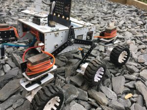
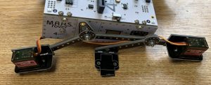
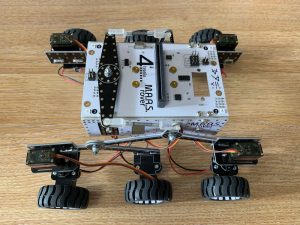
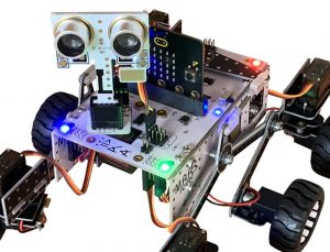
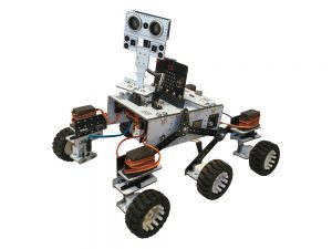
The 4tronix Mars Rover is loosely based on the Curiosity and Mars 2020 rovers from NASA. It uses the same rocker arm, bogey and differential arm mechanism.
Purchase M.A.R.S. Rover from here
Coding for the M.A.R.S. Rover for Microbit in Makecode here
Coding for the M.A.R.S. Rover for Pi Zero in Python here
Some stats on the 4tronix Mars Rover
- 6 Motors. 80 rpm 6V, N20 micro gear motors
- 4 Servos. MG90S metal gear analog micro servos
- Total number of special PCBs: 30
- Number of different PCB designs: 11
- Length: 200mm
- Width: 185mm
- Height without Mast and Microbit: 95mm
- Height with Mast: 170mm
Kit Contents
NOTE: The kits for Raspberry Pi Zero and BBC Microbit are identical, except for the mainboards which are slightly different. The assembly guide is the same, whichever one you have. ALl photos are for the Microbit version.
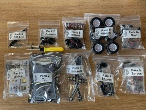
The kit is packed in 10 bags, which should be assembled in order as follows
- Side pack. PCBs and screws to assemble both side pieces of the main body
- Brains (Top) Pack. This PCB houses all the electronics and together with the side pieces (1) forms the structural body of the 4tronix Mars Rover
- Rocker Pack. These 2 rocker arms are pivoted on the screws fitted into each side piece. Each rocker arm carries a single servo for a front corner wheel assembly
- Bogey Pack. These two rear bogeys carry the centre and rear wheels for each side. The rear corner wheels are steered with a servo
- Servo Pack. This contains 4 metal gear micro servos together with screws to fix them into the Rockers and Bogeys
- Differential Arm Pack: The differential arm and couplers joins the two Rockers in such a way that it tries to keep the main body level (side to side) as one side or the other traverses uneven terrain. In earlier NASA Mars Rovers, this arm was replaced by a differential gear train, but the arm was found to be simpler and less prone to failures.
- Corner Wheels Pack. Each corner wheel is steered by its own servo. This pack contains the PCBs and screws needed to connect all four of the motor mounts to the servos
- Motors Pack. This includes the 6 motors, each ready-wired with a JST connector lead which plugs into the underneath of the main brains board. Plastic mounting brackets and associated screws are also included
- Wheels Pack: Six wheels. Just push them onto the motors. You must enusre that the D-shaped axle is aligned with the D-shaped hole in the wheel
- Mast Pack. Includes another servo, the mast base and a plug-in mast head with an ultrasonic sensor and some LEDs.
Assembly
You should allow 2 hours to build this if you are used to assembling kits of this nature. If it is your first assembly of something like this, then you may have to double the expected timeframe.
Step 0
Check you have all the bags described above. There is also a spares bag, a spare servo, a screwdriver and a wrench. The screwdriver has both a flat blade and a philips blade end. Pull out the metal part and insert it the other way round to change ends.
Step 1: Assemble the Sides
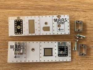
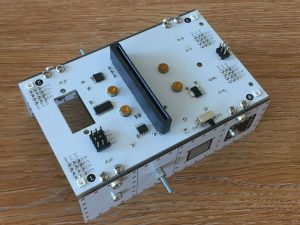
You should have two sides pieces (left and right), four aluminium brackets, eight 8mm M3 screws and two long 16mm M3 screws. Photo above shows 2 brackets fitted and two brackets ready to fit.
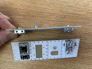
Screw the brackets into the side pieces from the inside as shown above. Make sure that the vertical screw holes in each brackets are next to the top surface of each side.
Then screw the long screw from the inside, through the PCB and through the fitted nut. Make sure all screws are tight as once it is assembled it will be very hard to get at them again
Step 2: Fit the Brains/Top to the Sides
You should have the Brains PCB and eight M3, 6mm screws (The Pi Zero version also has two M2.5, 6mm screws for fixing the Pi Zero to the pillars)
The sides should be fitted as shown above with the rocker mounting screw nearest the front (the end with the servo hole in the top/brains PCB)
Step 3: Fit the Rocker Arms
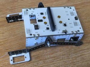
You should have two rocker arms (left and right) with servo mounts fitted, two M3 nyloc nuts and 4 M3 washers
Place a washer onto the rocker pivot screw, then place the rocker arm, then a second washer and finally the M3 nyloc nut. Tighten up the nut (using the included multi-wrench) as far as it will go, then back it off the tiniest bit until the arm moves freely. If you loosen the nut too much the arm will wobble, so get it as tight as possible without binding.
The servo carrier on each side is at the front of the rover, facing outwards as shown above.
Step 4: Fit the Bogeys
You have two bogeys (left and right) with servo and motor carriers attached, two M3, 10mm screws, 4 washers and two nyloc nuts.
Fit the screw from the inside, through the rocker arm, then a washer, then the bogey, then a second washer and finally the nyloc nut. As with the rocker arms, do the nyloc nut up tightly then back it off slightly so the bogey moves freely. Again, it is much easier to use the screwdriver to hold the screw in place, then turn the multi-wrench to tighten the nut.
The bogeys also have the servo carriers facing outwards in each rear corner of the rover.
Step 5: Fit the Steering Servos
You have four servos and eight 6mm, M2.5 screws.
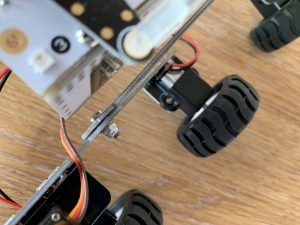
Mount each servo with the output shaft nearest the centre of the rover as shown above. Screw from underneath the servo mounting PCB into the holes on the side of each servo, as shown below. Keep hold of the servo arms and servo shaft screws, ready for Step 7.
Step 6: Fit the Differential Arm
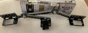
You should have the differential arm PCB, a long screw, 2 washers and a nyloc nut and 2 push-rods with 4 screw on snap links.
Screw the long screw from underneath, through the main board and into the fitted nut. Do up tightly.
Place a washer over the long screw and onto the fitted nut, then the differential arm, then the second washer and finally the nyloc nut. As with the rocker arms and bogeys, do up the nyloc nut tightly then slacken it off slightly
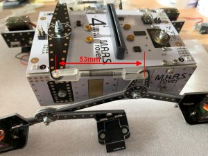
Finally adjust the pushrods and snap links by screwing in and out until the distance between the clip points is about 53mm. Then clip firmly into the top of each rocker arm and the ends of the differential arm.
When you have fitted the wheels (later) you can adjust the length of the pushrods to ensure that the body of the Rover sits level.
Step 7: Fit the Corner Wheel Mountings
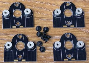
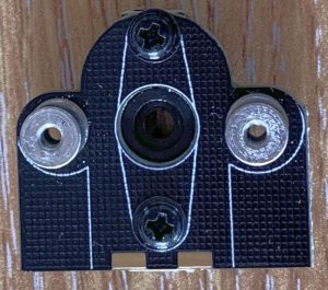
You should have four top pieces with 4mm nuts attached and eight 6mm black screws.
Also included is the Zero Servo – a little magic PCB that centres your servos without hassle.
You will also need the four cross-shaped servo arms and servo shaft screws from the servo packs. Do not use the longer screws in the servo packs. If the soldered nuts still have the orange kaptan tape on, you will need to peel it off.
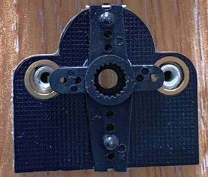
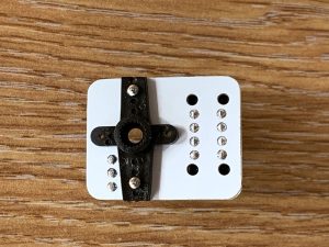
Fit the cross-shaped servo arms to the top pieces with the nuts attached. The arms fit on the opposite side to the nuts and with the hole that accepts the servo shaft facing outwards. Note that the arms are not symmetrical – so the holes will only line up properly one way round – the longer end goes towards the straight edge of the mounting PCB. You can use a pair of side-cutters (or nail clips?) to chop off the protruding ends of the servo arms.
IMPORTANT: it is important that the motors are mounted so they are pointing outwards at as close to 90 degrees as possible when the servos are set to 0 degrees.
Use a ServoZero (included) connected to power by a USB cable and plug each servo in turn into it to set to the zero position. We can fine tune the position later in software, but it is important to get it close mechanically.
After the the servos have been zeroed, then fit the motor mountings to the servo.
Use the little servo shaft screws from the servo packs to fit each motor mounting securely.
Step 8: Fit the Motors
You should have 6 motors with JST leads attached, 6 mounting brackets, 20 M2 screws and 12 M2 nuts. You will also have the 4 lower motor mount PCBs
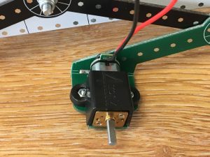
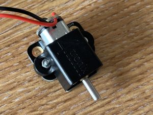
Mount the centre motors by fitting the nuts into the plastic brackets, then screwing through from underneath into the nuts. See photo above.
The corner motors are mounted by first fitting them to the lower motor PCBs from Pack 7 using 2 screws and 2 nuts for each.
Then screw the resulting assembly onto the 2 fitted 4mm nuts on the PCBs you assembled in step 7.
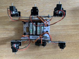
With all six motors fitted, attach the JST leads to the connectors underneath the main board. It doesn’t matter which connector you use as long as the left side connects to left motors and the right side connects to right motors.
You can use this opportunity to connect all the servo leads as well. These need to be connected to the servo connector nearest to them. So use 9, 11, 13 and 15.
You can wrap the spare lead around the servos to tidy the cables up a little. An alternative method that I use is to put the cables down the side of the battery holders underneath and hold them in with a peice of foam cut from the packing in the box.
Step 9: Fit the Wheels
The six wheels simply push on, but be careful to line up the D-shaped hole in the wheels with the D-shaped axle. Only push the wheel when holding the motor, not when hold the body.
It looks better (I think) if the wheels are on “backwards” with the spokes showing
Step 10: Fit the Mast
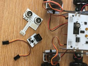
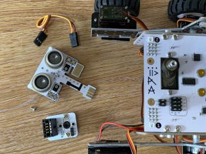
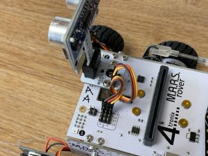
The mast houses an ultrasonic distance sensor and 2 White LEDs (not controllable). It is fitted onto a steerable servo and can be removed simply by unplugging it.
This pack contains the servo, the mast base PCB, the mast head PCB, two M2.5 screws to secure the servo and 4 short self-tapping screws to secure the servo horn to the mast base.
NB. Pi Zero version also includes two M2, 4mm screws to attach a standard Raspberry Pi camera (not included) to the Mast Head.
Fit the servo by screwing the M2.5 screws through the top PCB into the holes on the side of the servo. Connect the servo lead to position SV0 underneath.
Fit the cross-shaped servo horn from the servo bag to the bottom of the mast base PCB using the 4 small self tapping screws.
Fit it so that the connector is pointing forwards when the servo is at its centre position. Use the small shaft mounting screw in the servo bag to fix it firmly to the top of the servo shaft.
Then plug in the mast head and plug the 3-wire lead from the mast base to position P13 for Microbit (#23 for Pi Zero) on the top of the main board. Ensure the Brown wire is next to G on both boards.
Step 11: Fit the Microbit or Pi Zero
The Microbit should be plugged in with the LEDs facing forwards as shown above.
The Pi Zero (with header) should be plugged in facing downwards and to the rear of the Rover as shown above
Step 12: Fit the Batteries
You will need 4 x good quality rechargeable AA batteries. It is possible to use with alkaline batteries, but only when they are fresh. This applies particularly to the Pi Zero version, which requires additional current during booting that can only be supplied by rechargeable batteries. We recommend Eneloop or Energizer Extreme.
Complete!
Now for some coding using Microsoft Makecode: Makecode extension is from https://github.com/4tronix/MARS-Rover
In Makecode, click on Advanced, then Extensions. Enter the URL above into the search bar. See this guide.
For Pi Zero and Python, see this guide.

