Using the PiDie Raspberry Pi Addon Board

Overview

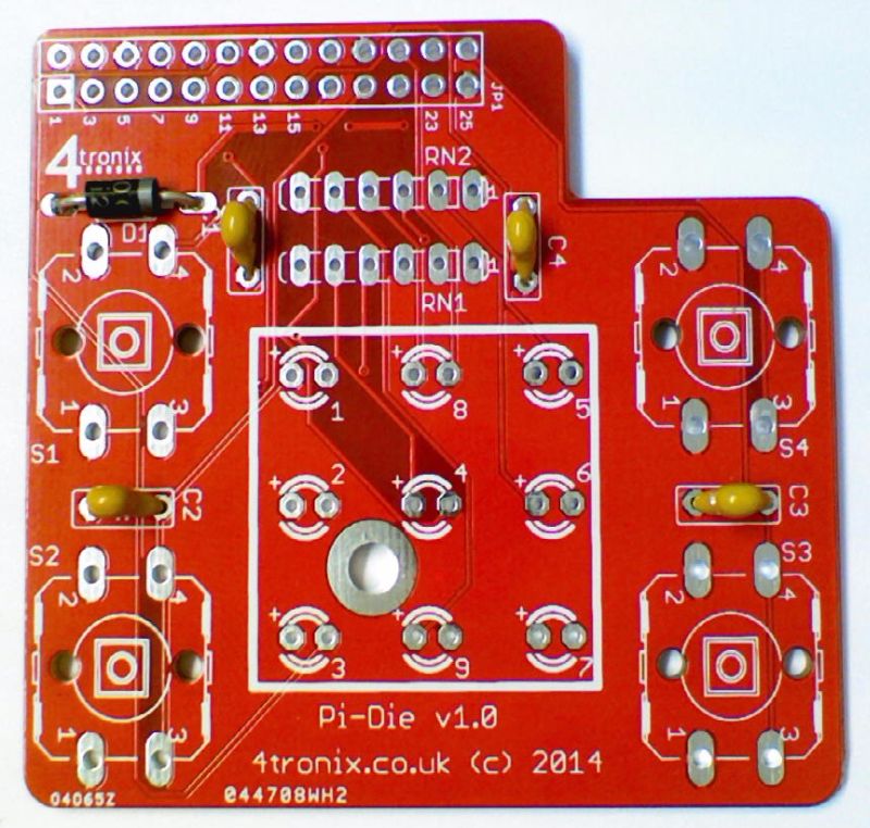
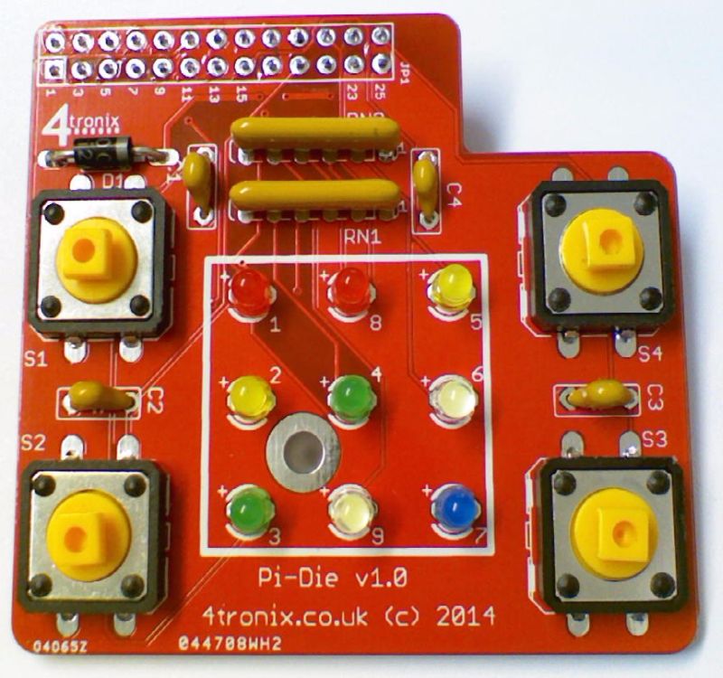
There are 9 LEDs arranged in a 3×3 matrix:

  • 1, 2, 3 down left side (Red, Yellow, Green – ideal for use as traffic lights)
  • 4 in centre (Green)
  • 5, 6, 7 down right side (Yellow, White, Blue)

These 7 LEDs then form the dots on a dice. The matrix is completed with LED8 (Red – top centre) and LED9 (White – bottom centre)

1  8  5
2  4  6
3  9  7

The Buttons are Red (top left), Green (bottom left), Yellow (top right), Blue (bottom right) and the colours match the colours of the LEDs in the same corners. Ideal for use in the Simon game,


Pin Connections

These refer to the physical pin numbers on the GPIO header. If using gpio module in python, then set the mode to “board”.

LEDs:

  • Led1: 7
  • Led2: 11
  • Led3: 12
  • Led4: 13
  • Led5: 15
  • Led6: 16
  • Led7: 18
  • Led8: 22
  • Led9: 8

Buttons:

  • Red: 21
  • Green: 19
  • Yellow: 24
  • Blue: 26


Use in ScratchGPIO

Download the excellent ScratchGPIO by Simon Walters from here.

  • Create a variable called “AddOn”. In the green flag black, set the variable to “PiDie”
  • The LEDs are named Led1 to Led9
  • To switch a LED on or off, you can send a broadcast message, or use variables.
  • Using broadcasts. Create a new message specifying what you want to happen. The syntax is “Led1On” or “Led1Off”. Change the number to select a different LED:
  • Using variables. You should create variables called Led1 to Led9. You can use the variable setting blocks to switch them on or off:
  • You can also set them all on or all off with a broadcast “AllOff” or “AllOn”


Use in Python

  • Import the GPIO library: import RPi.GPIO as GPIO
  • Set the GPIO mode to board: GPIO.setmode(GPIO.BOARD)
  • Set the LED pins as outputs: GPIO.setup(7, GPIO.OUT) // 7 is the for LED1. You need to do this for each LED, or use lists, etc
  • Set the Button pins as inputs: GPIO.setup(21, GPIO.IN, pull_up_down=GPIO.PUD_UP) // 21 is the for the Red button. You need to do this for each button, or use lists, etc
  • Note that in the line above we are using the internal pullup resistors. This is mandatory for the buttons to work.
  • You can then set an LED On or Off by setting the output to 0 (ON) or 1 (OFF): GPIO.output(7, 0)
  • You can check if a button is pressed with an IF statement: if GPIO.input(21):

Soldering the 4tronix PiDie Kit

Click on any image to enlarge it

Check you have all the parts

pd00

  • Printed circuit board (PCB)
  • 1 x Diode (not shown above)
  • 4 x switches
  • 2 x resistor networks
  • 4 x capacitors 100nF
  • 12 x LEDs (2 x red, 2 x yellow, 2 x green, 2 x white, 1 x blue)
  • 1 x GPIO 26-waye female header
  • Mounting assembly (10mm hex spacer, 2 x M3 screws, 1mm washer)

Starting Soldering

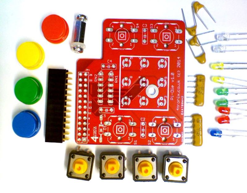
If you haven’t soldered before, you might want to check out this instructable. I find that the following order of soldering works best, starting with the lowest profile components and moving to the highest. This allows me to place the components through the holes in the PCB, then turn the PCB over onto the desk surface and gravity will hold the components in place. You can also use Blutack to hold the components in place while you solder


1. Add the diode

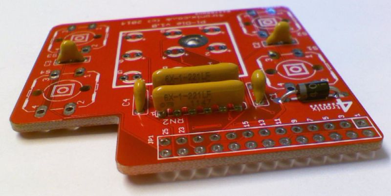
The black diode has a white/grey stripe on one end. this MUST match the marking on the PCB as shown in the photo below in the position D1

pd01


2. Add the 100nF Capacitors C1, C2, C3, C4

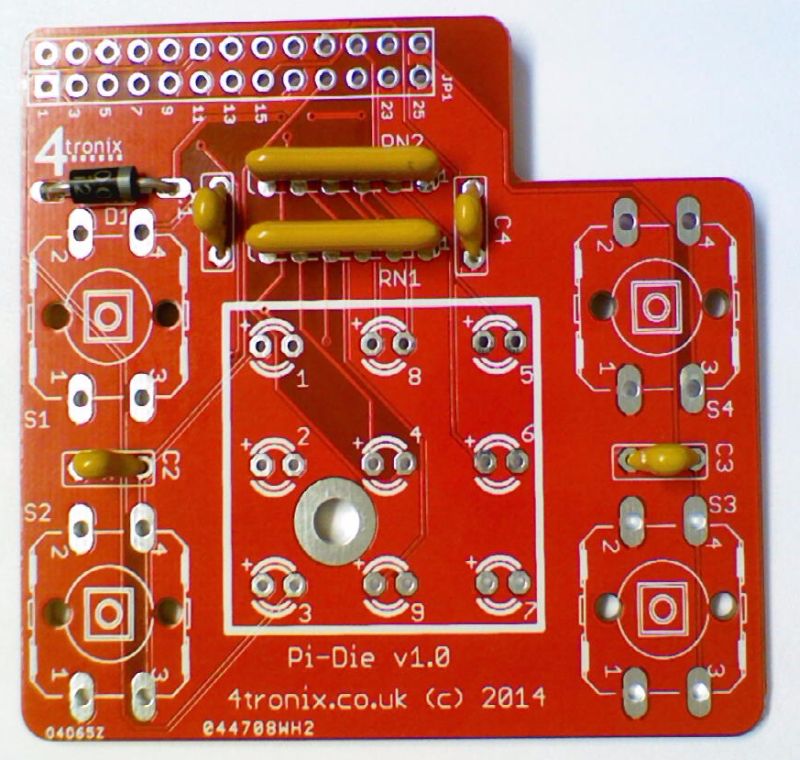
These are small, yellow and marked 104. It doesn’t matter which way round they are put in, but it is neatest if they point the same way. They fit into positions marked C1, C2, C3 and C4

pd02


3. Add in the resistor networks RN1, RN2

These must be soldered in the correct way round. Double check before soldering. The writing needs to be closest to the GPIO header location, with the black dot (for pin 1) next to the end marked on the PCB with a small ‘1’

pd04 pd03


4. Solder the switches

These may already be clipped into position when you receive the kit, because that protects them during shipping. However, they will not be soldered so you need to do that for them to work. It doesn’t matter which way round they go – they can fit in 2 positions.

pd05


5. Add in the LEDs

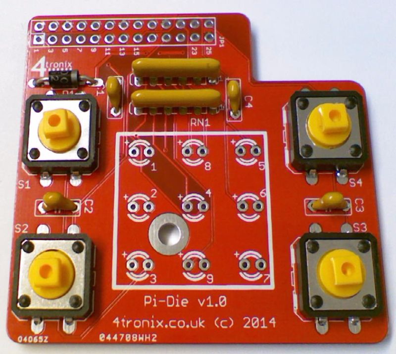
The LEDs must fit in the correct way round or they will not work. The long legs on each diode must go into the hole next to the + mark on the PCB. All LEDs are oriented the same way – so if you get one right, then all should be right.

Step04 led01 pd06


6. Solder the GPIO Header

This must be placed on the opposite side of the board to all other components. It is extremely difficult to remove them if soldered incorrectly, so please double check before soldering

pd07


7. Add the Caps for the switches

These can go any way round, Just carefully push on so they click in place

pd08


8. Screw on the spacer

Fit an M3 screw through the hole in the board, then add the 1mm washer, then screw on the 10mm hex spacer. You can then push the board onto the Pi and the spacer will keep the board stable when the switches are pressed. You can screw it onto the Pi if you like, or simply let it rest. Please don’t use this spacer if using a Rev A Pi (without the mounting holes) as there are components in that place which can be damaged,

Assembling and Using PiRingo

Purchase 4tronix PiRingo >here<

Parts Included

  • Blank PCB
  • 12 LEDs – various colours depending on design chosen
  • 3 resistor networks (5-pin)
  • 2 miniature tact switches (2-pin)
  • 2 capacitors (100nF) – optional
  • GPIO connector header
  • 11mm hex spacer and screws (10mm metal spacer plus 1mm washer)


Tools Required

  • Soldering iron
  • Side cutters (could use nail clippers if necessary)


Soldering Sequence

  1. First add the 3 resistor networks to positions RN1, RN2 and RN3 as shown below. These are black, labelled A221J and have a white dot near one end. The white dot must be at the pin marked with a ‘1’ and next to the component name (ie. RN1, RN2 and RN3)
    step01
  2. Note that an unused hole is left at the other end (this hole is to allow different components to be used if 5-pin networks become unavailable for any reason)
  3. Then add the 2 switches, one either side in positions SW1 and SW2. It doesn’t matter which way round these are placed
    step03
  4. If you are concerned about switch bounce you can add the two 100nF capacitors, C1 and C2. As they are included with the kit and not difficult to add, then we recommend that they are added. it doesn’t matter which way round they are fitted
  5. Then add the LEDs. These are all the same way round with the long lead next to the ‘+’ on the PCB. The LEDs will not work if they are connected the wrong way round, but no damage will occur. You can also tell the negative lead by looking inside the LED itself. The lead with the large triangular plate is the negative lead.
    Step04led01
    step05
  6. Finally add the GPIO connector. This must be added to the opposite side of the board!
    step06astep06b


Using the PiRingo

  1. Download example Python codes from our GitHub
  2. You can also view the PCB design schematic at the same location
  3. Download and install the Scratch GPIO v4 from @cymplecy
  4. Current example Python programs are:
    1. allon.py – switches all LEDs on
    2. alloff.py – switches all LEDs off
    3. flashdemo.py – goes through a sequence of flashing and chasing patterns. These are all coded as separate functions, so you can easily change to any sequence you require
    4. swing.py – moves a single LED under command of the two switches. See who can press the  switches faster
    5. swing2.py – creates a range of LEDs for the fastest switch presser – when the bar reaches the other side, the winner is declared with flashing lights!
  5. Current example Scratch GPIO programs are:
    1. Traffic lights simulation


Pin Definitions

The Pin numbers below refer to the physical pin numbers on the GPIO header. To use these pin numbers in Python, be sure to set the GPIO mode as “Board” as shown here:
GPIO.setmode(GPIO.BOARD).

All LEDs and switches are Active Low. So set an LED to 0 to turn it on, set to 1 to turn it off. Switches are 0 if pressed, 1 if not pressed

  • LED1 – pin 7
  • LED2 – pin 11
  • LED3 – pin 12
  • LED4 – pin 13
  • LED5 – pin 15
  • LED6 – pin 16
  • LED7 – pin 18
  • LED8 – pin 22
  • LED9 – pin24
  • LED10 – pin26
  • LED11 – pin 8
  • LED12 – pin 10
  • Switch 1 – pin 19
  • Switch2 – pin 21