CrumbleBot 2 and CrumbleBot XL – Assembling and Coding
Purchase CrumbleBot Mk2 here
CrumbleBot Mk1
If you are looking for information on the previous versions, please check the older blog entry here
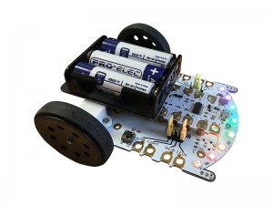
Updated Features
- 8 Addressable RGB LEDs (‘Sparkles’)
- Easy to use buzzer
- 2 push button switches
- Jumpers with handles, instead of crocodile/alligator clips
- “Wire-free”, low-profile battery holder (no USB connectors or wires to get broken)
- Modified motor mounting positions to reduce dust ingress into the gearbox
- Improved, smooth-running, front caster
- Powered front accessory connector
Assembling CrumbleBot Mk2 and XL
Click any photo to enlarge
Step 1 – Check you have the correct Parts
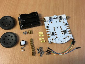
You should have the following items in the box:
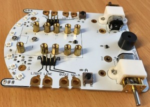
- CrumbleBot Mk2 or XL main circuit board
- 2 x Wheels
- Battery Holder PCB
- 10 x small 7mm pillars to mount Crumble (not required for version 2.1 or XL as pillars are pre-fitted)
- 2 x larger 12mm pillars to mount battery holder
- Caster ball and housing (Mk2 only – prefitted on XL)
- 2 x M2, 6mm screws to attach caster (Mk2 only)
- 2 x M2 nuts for caster (Mk2 Only)
- 10 x 4mm M3 screws (v2.0 has 20 x 5mm) to attach Crumble
- 4 x 8mm countersink head screws to fit battery holder
- 4 x Yellow (colour may vary) jumpers with “handle” to select function of each connection
- 4 x coloured 12cm jumper leads for when the little yellow jumpers can’t reach
Step 2 – Fit the Caster (Mk2 only)
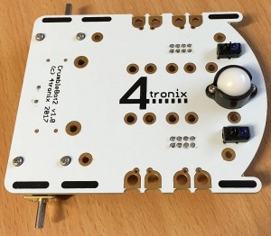
Use the 2 small M2, 6mm screws to pass through the caster underneath the CrumbleBot and fit the nuts on the top of the CrumbleBot mainboard.
Caster is pre-fitted on CrumbleBot XL
Step 3 – Fit the Crumble mounting Pillars (v2.0 Only)
NB. V2.1 and XL Has these pillars ready-fitted – skip this step
V2.0: Use 10 of the small 5mm screws to fit the 10 small pillars on the top of the CrumbleBot.
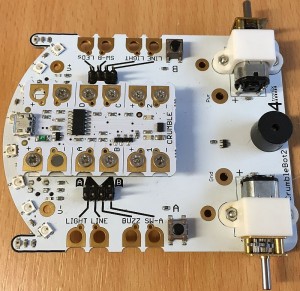
Step 4 – Fit the Crumble
Use the 10 M3, 4mm (for v2.0 use the remaining 10 small 5mm) screws to attach the Crumble to the 10 pillars fitted in Step 3.
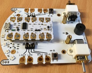
Step 5 – Fit the Battery Holder Pillars
Use the 8mm screws to fit the 2 longer 11mm pillars into the holes marked “GND” and “PWR”
Step 6 – Fit the Battery Holder
User the remaining 2 longer 8mm screws to fit the battery holder to the 11mm pillars.
NB. Ensure the switch and LED are at the rear of the robot
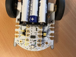
Step 7 – Add the batteries and Jumpers
A good starting point for the jumpers is in the middle two positions on the left side, and the outer two positions on the right side. This allows use of the line sensors, sparkles and buzzer without changing anything.
CrumbleBot XL has an extra position on the left side. This to enable the ultrasonic sensor and connect it to I/O pin A
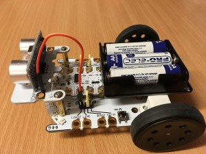
Step 8 Optional – Add the Ultrasonic Distance Sensor
Using the four 6mm screws, screw the two 20mm (11mm on XL) pillars into the front accessory connectors. Then screw the sensor module onto the top of the the two pillars as shown above.
For Mk2, to connect the sensor to the Crumble, you must use one of the 12cm jumper wires to connect to a GPIO pin. On XL use the yello jumper in its most forward position
All our examples use GPIO A so wire it as shown in the photo above. (Mk2 only, remember to remove the Yellow jumper attached to GPIO A). Now you can use the distance block in the Crumble software, setting both T (Trigger) and E (Echo) to the same pin. A in this case.
Your CrumbleBot Mk2 or XL is Finished and ready for Coding!
Coding Your CrumbleBot
1. Understanding the Jumpers
The Crumble has 4 general purpose IO (GPIO) connections, labelled A, B, C, D. These are all interchangeable for everything except driving Sparkles, which can only be done using GPIO D.
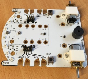
CrumbleBot Mk2 brings each GPIO connection to 2 positions on a jumper block and the XL adds another position for I/O pin A. The other side of each position is connected to one of the functions of the CrumbleBot. Thus, you can use the little Yellow jumpers to connect from a GPIO to one of the functions on the CrumbleBot2. For instance the top row on the left-side connector block is connected to to GPIO A (on the right of the connector block) and to the left side Light sensor (on the left of the connector block). Fitting a Yellow jumper across the top row will therefore connect the light sensor to GPIO A. If instead you connect the yellow jumper to the next row down, you would be connecting GPIO A to the line sensor. (As an aside, it is possible to connect each GPIO to 2 different signals at the same time – this won’t damage anything but will give unexpected results).
So the default settings for the yellow jumpers will connect the GPIO as follows:
- A to the left Line sensor
- B to the Buzzer
- C to the right Line sensor
- D to the 8 on-board sparkles
2. Driving the Motors
The Crumble has its own motor drivers which are connected directly to the motors on the CrumbleBot. You do not need to make any special connections to make these work. Each Motor is driven independently and you can select the speed (0 to 100) and direction (Forward or Reverse) in your code.
To drive the CrumbleBot2 forward, you would set each motor to the same speed Forward:
And to drive the CrumbleBot in reverse, you could set each motor to the same speed Reverse:
If both motors are going the same speed, but opposite directions, then the CrumbleBot2 will turn on the spot:
If the motors are turning different speeds, then the CrumbleBot2 will drive in an arc
3. Flashing the LEDs
The LEDs on the CrumbleBot2 are called “Sparkles” in Crumble-speak. You can easily code them to flash different colours using the colour-picker, or by setting different Red-Green-Blue (RGB) values.
First of all, make sure that GPIO D is connected via a jumper to “LEDs” – this is the default setting of the yellow jumpers.
This bit of code continuously makes all the LEDs flash Green on and off:
Of course, you can set each Sparkle to different colours and brightnesses – they do not have to be all the same. The following code implements a “Larson Scanner” famous from the KITT car in the Knight Rider show. It’s a bit complicated, but bear with it.
4. Following a Line
The CrumbleBot2 has built-in, digital, line following sensors. Make sure that the jumpers are set to connect GPIO A to the left line sensor and GPIO C to the right line sensor. This is the default setting. The following code drives forward until one of the sensors detects a line, then it turns toward the line until the line is not detected any more. This is a very inefficient “way to do it” (algorithm). Can you find a better algorithm for following lines?
You should make the black line out of something that doesn’t reflect light, with the background being a good reflector. Black electrical tape is good and so is printing black lines on a laser printer – here is a good resource for printing line-following tracks.
5. Making a Buzz
The CrumbleBot2 contains a little buzzer (small, round and black, underneath the battery holder). This buzzes loudly (quieter if the sticker is left on the top!) when the input is set to Hi.
The default jumper settings have the buzzer connected to GPIO B, so the following code makes an annoying beep every second:
6. Acting on Switches
There are 2 switches on CrumbleBot2 SW1 (A) on the left side and SW2 (B) on the right side. You will need to move the jumpers from their default positions to use them. The following code modifies the buzzer code in 5. “Making a Buzz” so that it waits for SW1 (A) to go HI (pressed) then starts the buzzer until SW2 (B) is pressed. You will have to use a 12cm jumper wire to connect GPIO A to the SW1 (A) – not forgetting to remove the yellow jumper. So this should have:
- 12cm Jumper wire from GPIO A to SW1 (A)
- Yellow Jumper from GPIO B to BUZZ
- Yellow Jumper from GPIO D to SW1 (B)
7. Following the Light
CrumbleBot2 has 2 light sensitive transistors which produce an analog value from 0 (very dark) to 255 (very bright).
We can use a similar program to the line follower. What we want to do is turn the robot to the side that has the most light. Because the light sensors can vary a lot, we must be careful that we don’t turn the robot every time there is a very slight difference in light levels, otherwise it would spend all its time turning and never move forward much. So we create a guard band in the software and make sure the light levels are sufficiently different before we decide to turn the robot. This is why we compare the X and Y variables and make sure there is a difference of at least 10, before turning.
Connect the yellow jumpers for GPIO A and GPIO C to Light
8. Use the Distance Sensor to Follow You around
Using the optional ultrasonic distance sensor, we can make the CrumbleBot2 follow us and stay the same distance away. The following code measures the distance to an object (eg. your feet). If it is too far away then the CrumbleBot2 moves Forward. If it is too close, then it moves in Reverse. This is a simple way to make a robot “friend”

