|
|
1. Check that you have all parts
- 2 x 28BYJ-48 5V Stepper motor
- 2 x ULN2003 Stepper motor driver board
- 2 x Wheel, 50mm diameter
- 1 x 4-cell battery box with on/off switch
- 1 x Table-tennis ball
- 1 x Plastic bottle top
- 1 x 400 tie-point breadboard with dual power rails
- 12 x Male-Female Dupont wires
- 2 x Double-sided adhesive pads
- 1 x ATMega328P-PU Arduino chip with Bootloader and Demo sketch
- 2 x 47µF electrolytic capacitor
- 2 x 22pF ceramic capacitor
- 1 x 16MHz crystal
- 1 x 10kΩ resistor
- 2 x Light dependent resistor (LDR)
- 30cm Red hookup wire
- 30cm Black hookup wire
- CP2102 USB Module (optional)
|
|
|
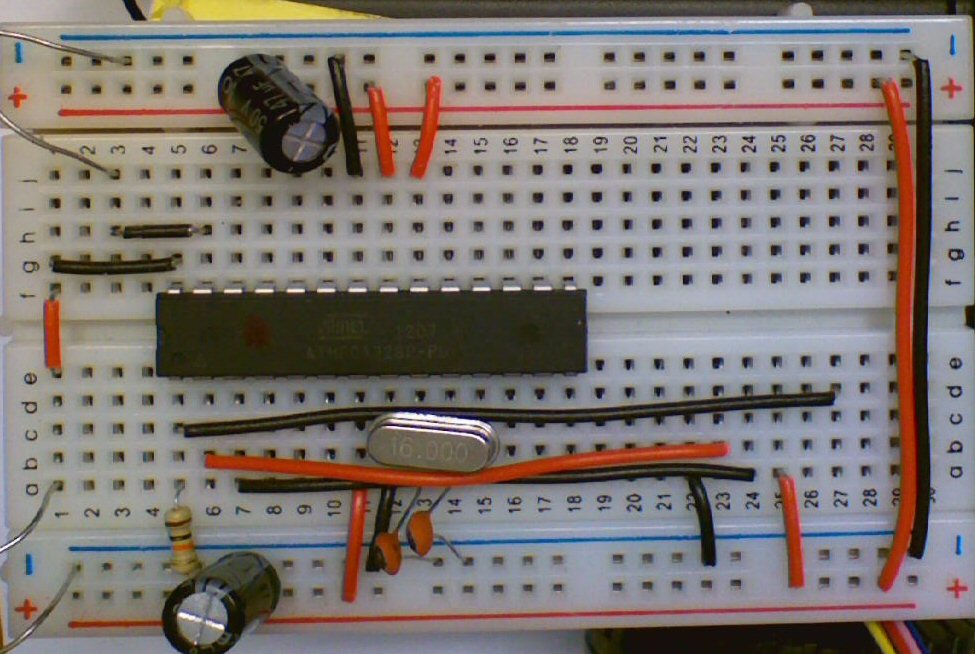
- Click on image to left to supersize
- Plug the ATMega328P-PU chip into the centre of the board so that Pin1 is on row 5 and Pin14 is on row 18
- Use the hookup wire to connect the points as shown (NB. Row22..27 is for the CP2102 module)
- The small 47pF capacitors connect Row 13 and Row 14 to the Negative rail
- The crystal is connected diagonally between Row 13 and Row 14
- Use the two 47uF capacitors to smooth the power on each power rail. Ensure you connect the negative end to negative rail
- The 10K resistor goes from Row 5 to the Positive rail
- The Left side LDR connects between negative rail and Row 1
- The Right side LDR connects between negative rail and Row 3
- Bend the LDRs so they are pointing 45 degrees left and right
|
|
|
3. Glue the Stepper Motors to Battery Box
NB. Ensure you glue these to the side shown, or access to the batteries will be very difficult
- Important: roughen the surfaces to be glued with sandpaper and blow away the dust, before gluing
- We used superglue Gel, but you can also use hot-melt glue. Do not use the very thing superglue as this probably will not hold and may get into the stepper motors and stop them operating
- Glue each stepper motor using the blue plastic connector the to very back of the battery box on the opposite end to the On/Off switch
- Leave these a few minutes before progressing
- Then glue the flat top of the bottle cap to the centre front of the battery box, to the side of the on/off switch. Fix this as far forward as you can - we have overlapped the front of the battery box
- Carefully push the wheels on a little way, ensuring that you hold the stepper motor and do not put any strain on the glued joints
- Now you can put glue around the edge of the bottle top and turn over onto the ping pong ball so that the weight of the assembly holds the ball while the glue dries
|
|
|
4. Fix the Breadboard and ULN2003 Boards
- Clip the top of the battery box on
- Either remove the batteries or switch OFF (or both!) - Do not have power on when connecting components.
- Remove the self-adhesive back strip from the breadboard and press it onto the top of the battery box so that Row1 overlaps the front and DOES NOT stick to the base of the battery box at the rear
- Check that you can still remove the battery box top to change batteries
- Connect the cable from each stepper motor into a ULN2003 control board
- Use the double-sided adhesive pads to stick the control boards to the back of the battery box
- Then use the Female-Male Dupont wires to connect the ULN2003 to the breadboard:
- Right motor IN1 to Row18 (left)
- Right motor IN2 to Row18 (right)
- Right motor IN3 to Row17 (right)
- Right motor IN4 to Row16 (right)
- Left motor IN1 to Row10 (left)
- Left motor IN2 to Row15 (left)
- Left motor IN3 to Row16 (left)
- Left motor IN4 to Row 17 (left)
- Connect the power lines from the motors to Negative and Positive on the breadboard - ensuring you have them the correct way round!
- Connect the Red (positive) and Black (negative) from the battery box to the Negative and Positive on the breadboard
|
|
|
5. Time to check it out
- NB. DO NOT CONNECT THE USB CABLE AT THE SAME TIME AS THE BATTERY BOX IS SWITCHED ON
- There is no protection on the board for multiple power suppliers. Be VERY VERY careful not connect both power supplies at the same time
- DO NOT USE ALKALINE OR NON-RECHARGEABLE BATTERIES
- There is no regulator on the board and non-rechargeable (1.5V) batteries will provide too much voltage for the ATMega chip. You may be lucky, but don't risk it.
- If the robot does not start moving as soon as you switch it on, pull out the battery pack wires from the breadboard immediately
- The sketch running in the Arduino can be found HERE
- This demo will move forwards only, varying the speed of wheel nearest the light so that it moves that way
- There is another demo HERE which just moves the robot Forwards, Backwards, spin left and spin right
|