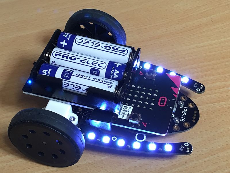
Bit:Bot and BitBot XL – The Integrated Robot for BBC Micro:Bit

BitBot Programming in Makecode: visit here
BitBot Programming in Python: visit here
The Following Text Refers only to BitBot Classic
A great way to engage young and old kids alike with the BBC micro:bit and all the languages available. Both block-based and text-based languages can support the Bit:Bot
You can also use the Radio or Bluetooth functionality of the Micro:Bit to send and receive commands and date. See a Bluetooth tutorial here
Warning: On versions before v1.2, the line follower sensors share the same pins as the buttons. Depending what language you are using, when the Micro:Bit is started or reset it will check the 2 buttons and start pairing if they are both pressed. With the Bit:Bot, this translates to both line follower sensors getting reflections. You can stop it happening by lifting it off the surface before switching on. On v1.2 the line sensors are disabled for 2 seconds after power on so that the MicroBit doesn’t detect the pairing situation. In addition there is a small switch that allows you to disable the line follower sensors completely, allowing the use of the MicroBit buttons.
Features
The Bit:Bot gives you all these features:
- 2 micro-metal gear motors. Both fully controllable in software, for both speed (0 to 100%) and direction (forward or reverse)
- Wheels with rubber tyres for maximum grip
- 12 mini neopixels in 2 sets of 6 along the arms either side. Select any colour for any pixel, produce stunning lighting effects as your Bit:Bot moves around
- 2 digital line following sensors. Code your own line-following robots and race them to see whose code produces the fastest lap time!
- 2 analog light sensors (front left and front right) so your Bit:Bot can be programmed to follow a light source such as a torch, or you could code it to go and hide in the darkest place it can find
- Buzzer, so you can make beeping sounds whenever you want
- Powered from integrated 3xAA battery holder with on/off switch and blue indicator LED
- Easily plug your BBC micro:bit in and out using the edge connector
- Extension port for additional neopixels (such as McRoboFace)
- Expansion connections at the front for additional sensors (eg. ultrasonic distance sensor, Talon grabber)
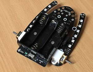
Assembling
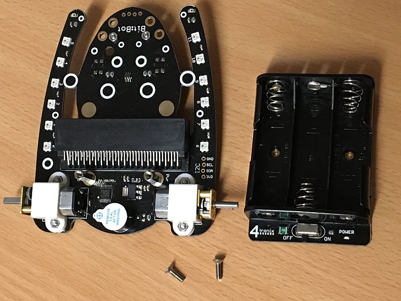
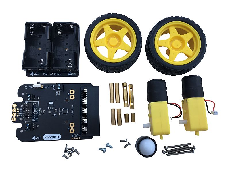
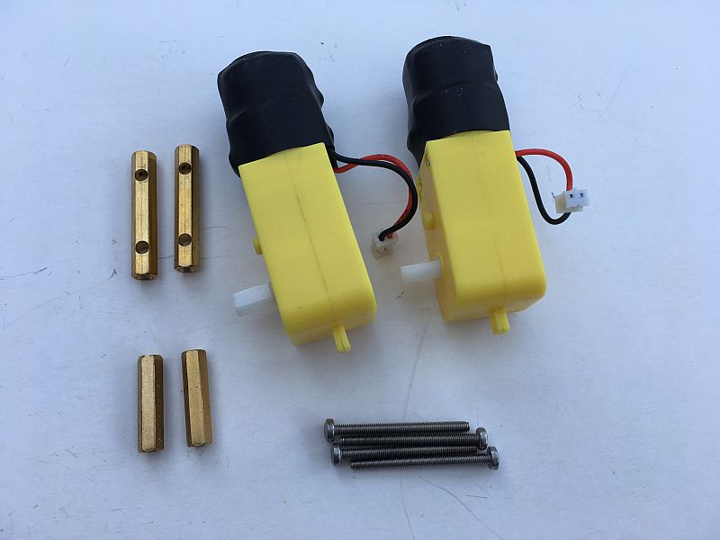
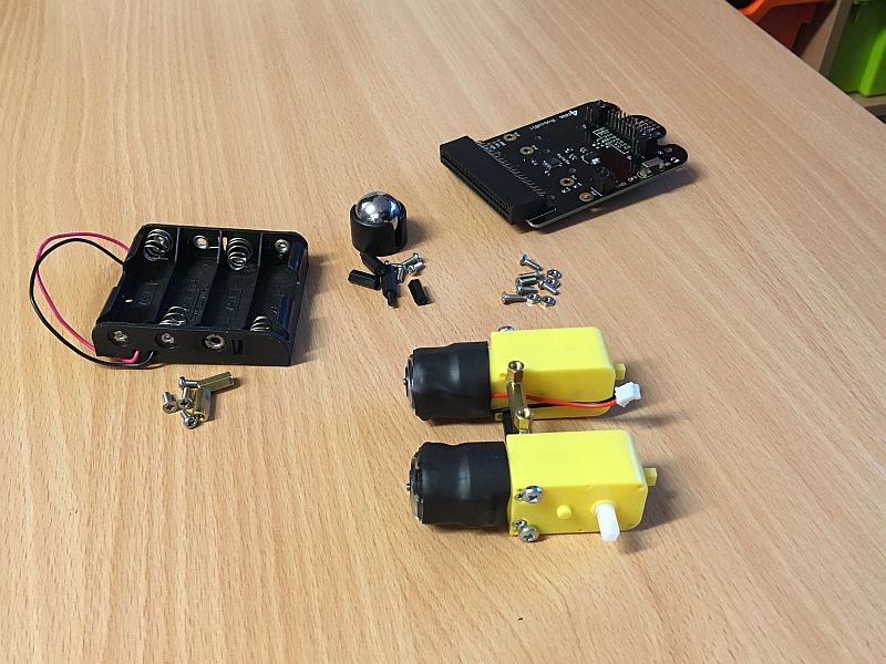
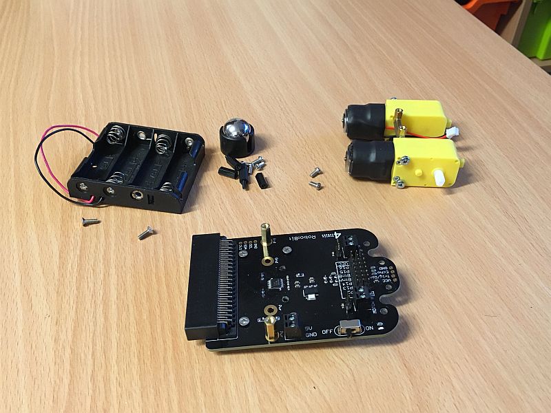
Step 0 – Check you have all the correct parts:
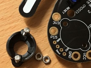
- 1 caster assembly (either metal ball or plastic ball)
- 2 x 6mm M2 pan head screws (now already fitted)
- 2 x M2 nuts (now already fitted)
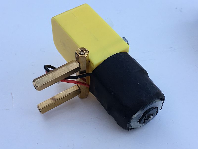
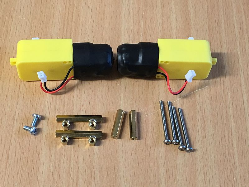
- 2 x 12mm brass pillars
- 4 x 8mm M2.5 countersunk screws
- Use the M2 6mm (panhead) screws and nuts to attach the front caster housing, then push the caster ball into the housing
- Use the M2.5 6mm panhead and 8mm countersunk screws to fit the battery pack onto the 2 metal pillars: ENSURE the on/off switch is at the rear of the Bit:Bot
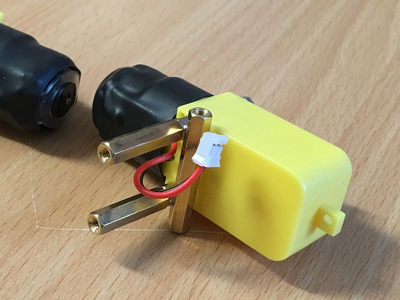
- Push the wheels on with the smooth side outwards. The axle should come flush with the outside of the wheel and not protrude (or the inside can catch on the motor housing)
- Push your BBC micro:bit into the edge connector with the LEDs and switches on the top
Click on any image to enlarge
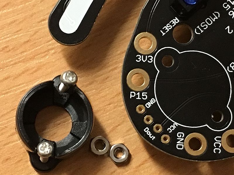
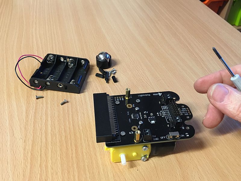
Step 1 – Fit the Front Caster (already fitted to current models)


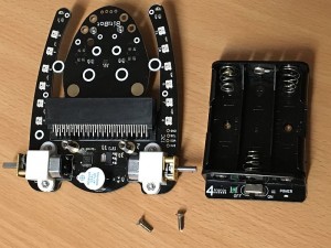
Step 2 – Fit the Battery Holder
At this point you should have 4 screws left. Either 4 x 8mm countersink, or 2 x 6mm panhead and 2 x 8mm countersink.
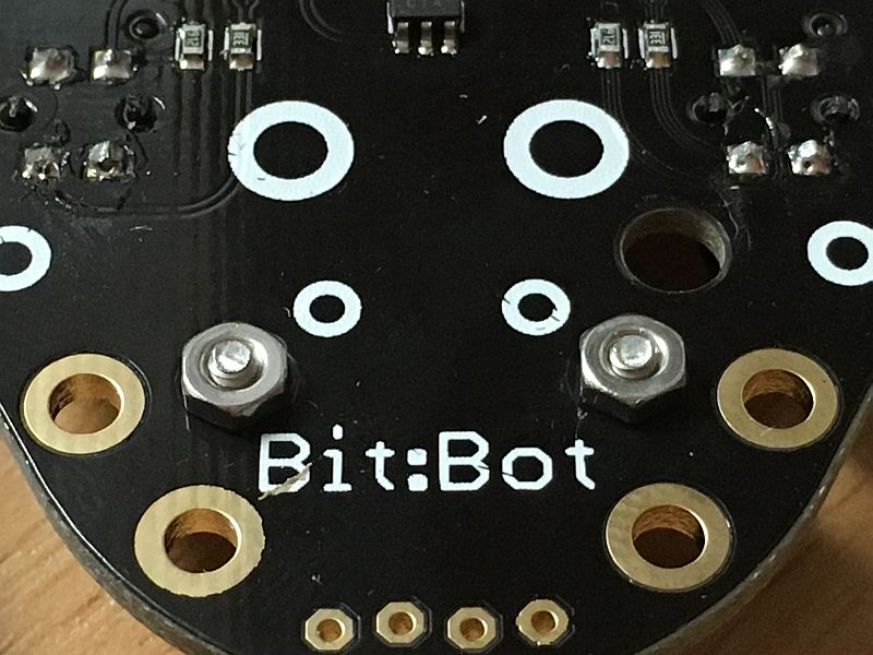
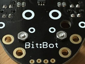
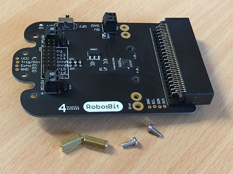
If you have the 6mm panhead screws, use these to fit the 12mm brass pillars to the Bit:Bot main PCB.
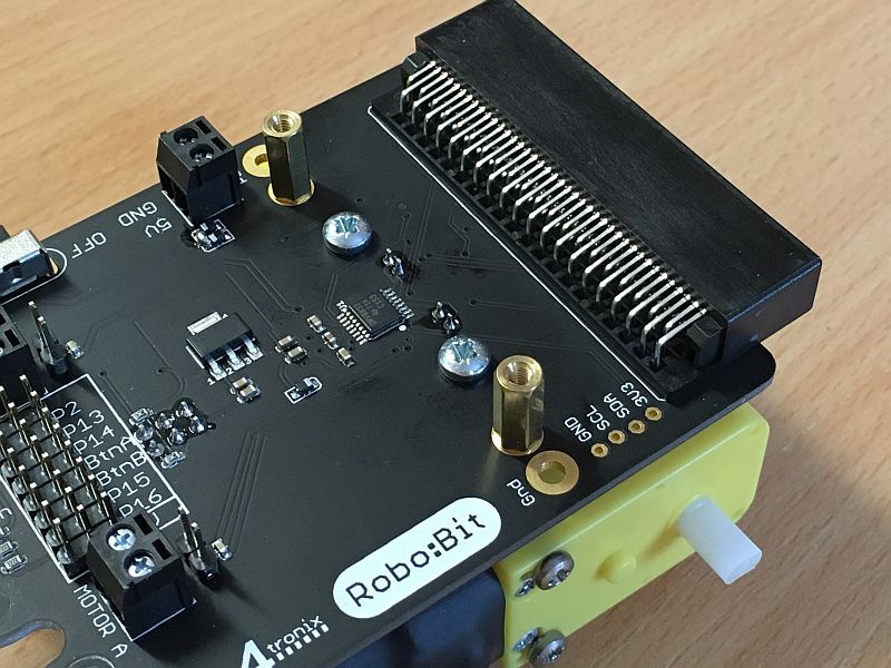
Always use 8mm countersink screws to fit the battery holder to the brass pillars.
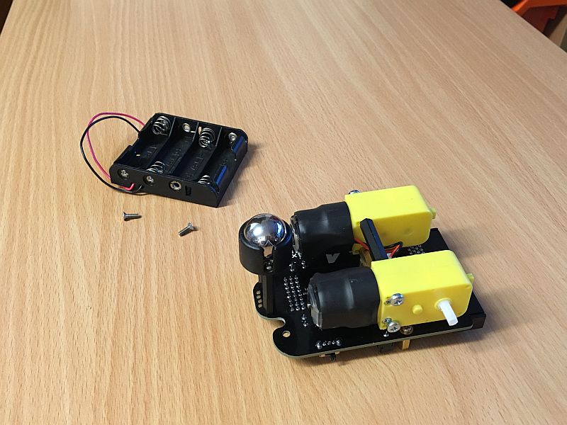
Use either 6mm panhead or 8mm countersink to fit the 12mm brass pillars to the main board (above)
Use the 8mm countersink screws to fit the battery holder to the brass pillars.
Step 3 – Fit the Wheels
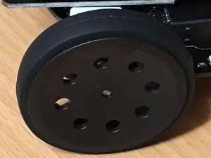
Push the wheels on, so that the axle is flush with the outside of the wheel
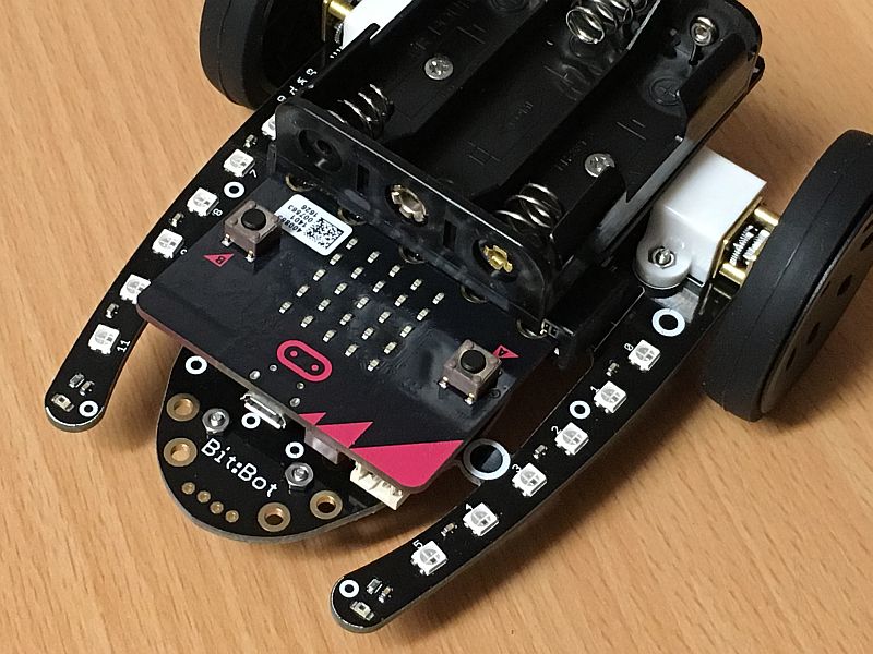
Step 4 – Attach your BBC micro:bit

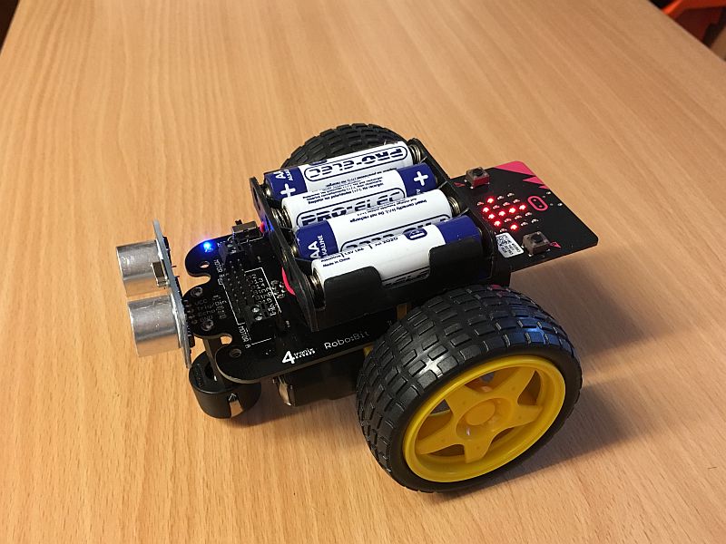
Know Your Bit:Bot
Above
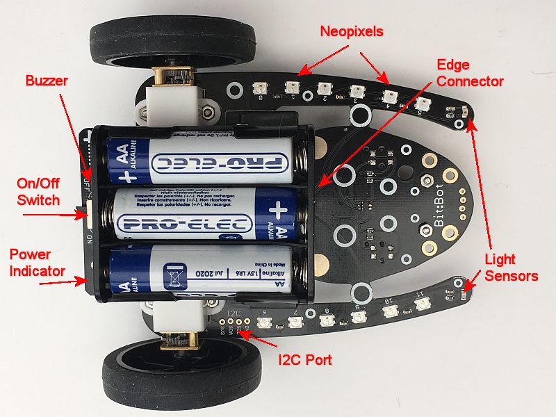
This shows the neopixels (6 on each arm), the 2 light sensors, on/off switch and indicator LED
The buzzer is below the on/off switch and the edge-connector is below the front of the battery holder
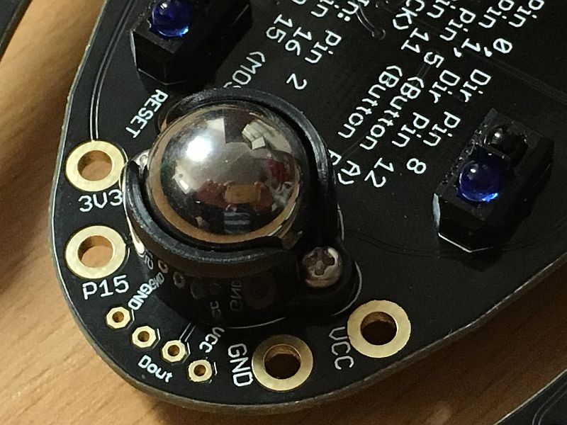
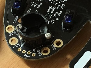
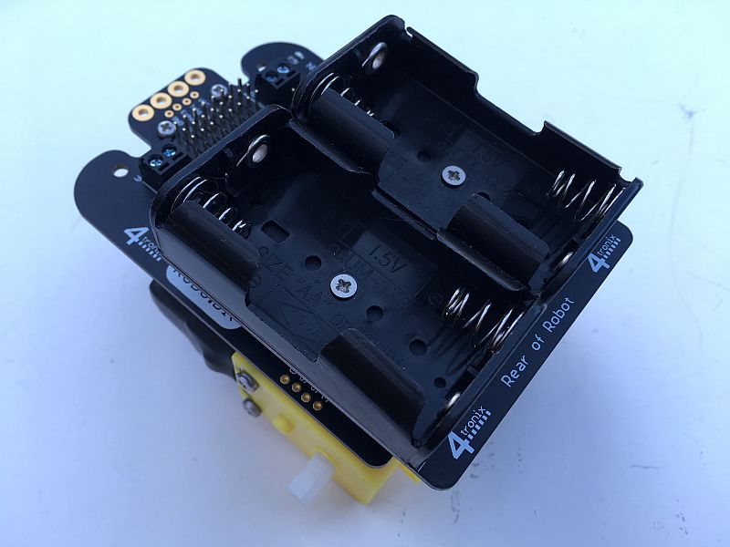
Below
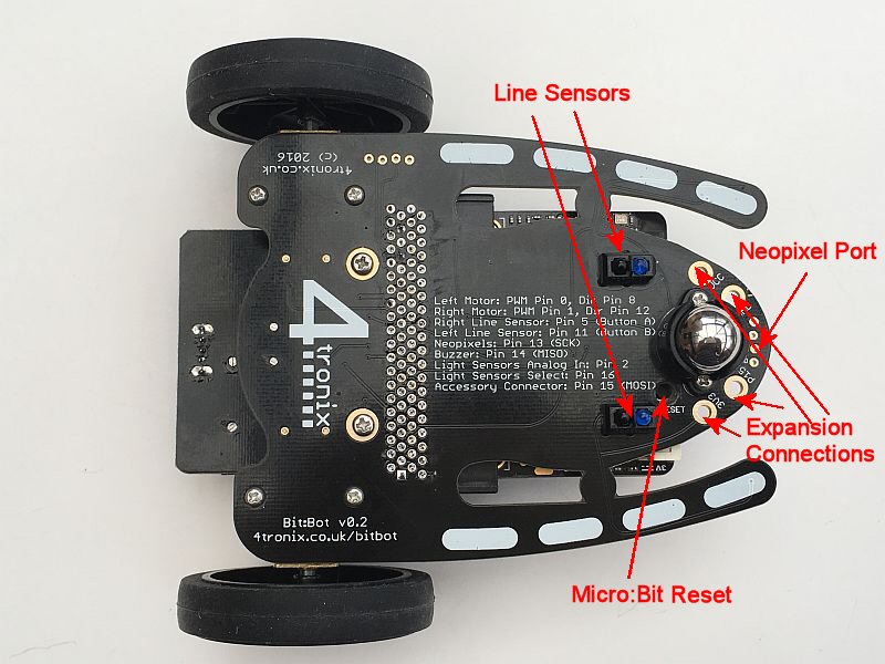
Now you can see the 2 line sensors and the port for neopixel extensions and general purpose expansion connector. Connection labelling is on the underside
Programming in Microsoft Makecode
Visit this blog for Makecode programming
For Makecode block programming, you can use the official BitBot extension. Go to the Advanced tab (or press the cog icon) and select Extensions. Then search for BitBot and select the official package. This will give you a BitBot tab in the toolbar with 4 sub-categories for the Motors, Sensors, LEDs and advanced (…more).

For text-based programming there is micro-python, and I prefer to use this offline using the Mu editor. It provides a very neat and easy way of interfacing to the micro:bit without all the fuss of dragging and dropping. NOTE: At the time of writing (December 2016), there are problems with Mu when using PWM with neopixels and other things, so it best to use the online micropython editor for now.
The following examples use both of these languages to show code fragments.
Note on examples: We want to show people how the various features can be used. We don’t want to do the coding for you – that is the learning experience you should be taking away from using it. In the following examples, we will give you the tools to use all the features of Bit:Bot but it is up to you to combine them together in your code to make it do something useful. We do give a complete example of line-following – but it is a very basic algorithm and will get confused at T-junctions and crossings; and it doesn’t use the neopixels.
Download Python examples at the bottom of this page.
Some great tutorials/examples by Mark Atkinson here
Motors
Under the Motors tab there are 5 blocks available as shown:

The first one “drive at speed 600” simply turns both motors at the speed selected between 1023 and -1023. 1023 is full speed forwards and -1023 is full speed backwards. Setting the speed to 0 will stop both motors.
The second one will do the same, but then stop both motors after the time selected.
The next two “spin <left> at speed 600” will spin the BitBot on the spot by turning one wheel at the selected speed forwards and the other at the selected speed backwards.
The final block allows you to control the individual motors. Either the left motor or the right motor (or both). This is so that you can make a long sweeping turn instead of spinning on the spot, by making one motor go slower than the other.
LEDs
A great feature of the Bit:Bot is the set of neopixel LEDs, 6 down each arm.
The Makeblock extension supports these easily

The LEDs category has the basic blocks as shown above, but there are additional advanced blocks in the “…more” category
Normally, the process to update LEDs is a 2-stage process:
1. Make the changes to the LED colours (eg. “set all LEDs to Red”)
2. Send all the changes to the LEDs (“show LED changes”)
However, we have made it so that the default is “automatic updates”, so any changes made to the LED values will automatically result in the LEDs changing. This is a slower way to do things, but much easier to understand. If you want the normal, manual, update method then this can be selected from the “…more” category.
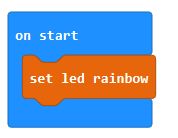
You can get a simple rainbow pattern on all the LEDs with just the “set led rainbow” block
And by using the forever block you can get the LEDs to animate using “rotate LEDs” and a pause to slow them down.

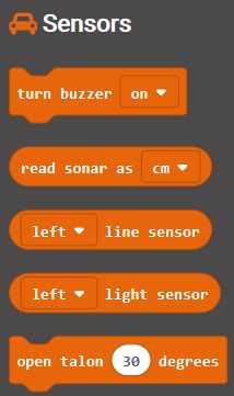
Sensors
The Sensors category provides access to both the integrated features (buzzer, line follower sensors, light sensors) and the optional addons (ultrasonic distance sensor, Talon grabber)
Buzzer
The “turn buzzer on/off” block enables you to make a simple beep

The program above will make a very annoying beep, beep, beep sound forever…
Ultrasonic Distance Sensor (sonar)
The “read sonar as cm/inches/microseconds” block enables you to read the distance from the front of the Bit:Bot to the nearest obstacle. Don’t expect this to be stunningly accurate, but it is good enough for obstacle avoiding etc. Here is a very simple obstacle avoiding program
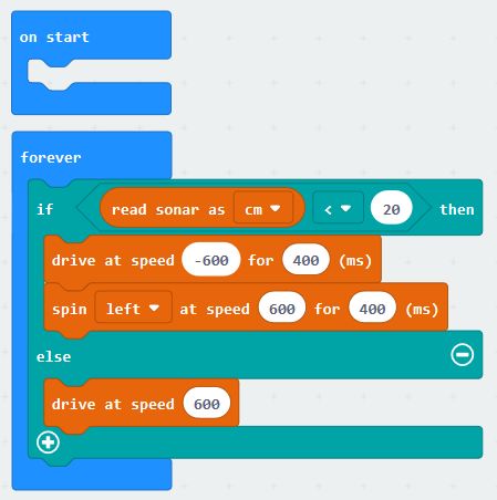
In this program it reads the distance in centimetres. If it is nearer than 20cm then it reverses and turns, otherwise it carries straight on.
Line Following Sensors
The idea of these sensors is that you create a black, non-reflective, line on an otherwise reflective surface. You can then program the Bit:Bot to follow the line.
The best way to get a good line is to print a track on a laser printer. We use these printable tiles which are excellent

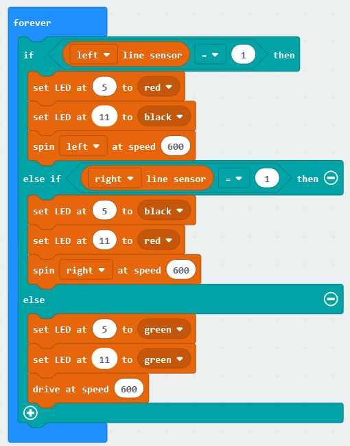
This is a very simple and very inefficient line follower program. But it works. If the left line sensor detects a line then spin left, if the right line sensor detects a line then spin right. Otherwise carry straight on. You can add some LEDs to the program to make it more interesting. Here we have a Red LED on the end of each stalk if it is turning that way, or 2 Green LEDs if it is going straight
Programming in Python
Visit this link for programming in Python
For text-based programming there is micro-python, and I prefer to use this offline using the Mu editor. It provides a very neat and easy way of interfacing to the micro:bit without all the fuss of dragging and dropping.
Note on examples: We want to show people how the various features can be used. We don’t want to do the coding for you – that is the learning experience you should be taking away from using it. In the following examples, we will give you the tools to use all the features of Bit:Bot but it is up to you to combine them together in your code to make it do something useful. We do give a complete example of line-following – but it is a very basic algorithm and will get confused at T-junctions and crossings; and it doesn’t use the neopixels.
Download Python examples at the bottom of this page.
Some great tutorials/examples by Mark Atkinson here
Motors
Each motor has two pins connected to it. One determines the speed and the other the direction:
Left motor: Speed Pin 0, Direction, Pin 8
Right motor: Speed Pin 1, Direction Pin 12
The simplest way to make the motors move is to set the Speed pin to HIGH and the Direction pin to LOW (to move full speed forwards)
Move left motor Forwards:
pin0.write_digital(1)
pin8.write_digital(0)
Move left motor Reverse:
pin0.write_digital(0)
pin8.write_digital(1)
If we want to change the speed of a motor, so that it is not going at full speed all the time, we need to use PWM (Pulse Width Modulation). This is means of changing the amount of power given to the motor by switching it on and off very fast. The percentage value of PWM determines the amount of each cycle that the output is ON. So a percentage of 100% is the same as being on all the time and thus the same as the examples above. A percentage of 50% would mean that the motor is only energised half the time, so it will go much slower. Note that the actual speed of the motor is not the same as the percentage of PWM – the motor won’t turn at all if the PWM value is too low and you will also get some stuttering at certain values. Nevertheless, being able to change the speed makes for a much better robot. For example, you can make a line follower that smoothly follows the line, rather than the normal shaking left and right.
To change the PWM value of a pin, we must use the analog_write commands. These can be set to a value between 0 (always off) to 1023 (always on), so 50% would be 511. Here are the commands to change the speed of the Right motor to approx 75% (value is 770)
Move right motor forwards at 75%
pin1.write_analog(770)
pin12.write_digital(0)
Doing this for the motors moving in reverse is a little confusing. Remember we need to change the direction pin to 1 for reverse. Then we need to set the amount of time in each cycle that the speed pin is LOW. This is the opposite of moving forwards, where we set the time for it to be High. Se we simply take the number (770 in this case) away from 1023, giving 253:
Move right motor Reverse at 75%
pin1.write_analog(253)
pin12.write_digital(1)
Neopixels
In fact, the name “neopixel” is a termed coined by Adafruit, but like “hoover” was a name of a brand of vacuum cleaner and is now a general term for all similar products, whoever makes it. The generic term is “smart RGB pixel” and is usually referenced with the name of the chip WS2812B. However, there are many different chips, all performing in a compatible way. The ones on the Bit:Bot are actually SK6812-3535
These smart RGB pixels are able to display any of 16 million colours by selecting a value of 0 to 255 for each of the Red, Green and Blue LEDs on each chip. The whole thing is controlled by a single pin on the BBC micro:bit (pin 13 for Bit:Bot). It is simple to use the included neopixel libraries to control each pixel individually.
The pixels are labelled on the Bit:Bot. From 0 to 5 on the left arm and from 6 to 11 on the right arm. If you connect any more neopixels into the extension port, then the new ones will start at 12.
Set neopixel 2 to purple (red and blue)
import neopixel
np = neopixel.NeoPixel(pin13, 12)
np[2] = (40, 0, 40)
np.show( )
The first line imports the neopixel library. We only need to do this once, at the very top of your Python programThe second line creates an Python list with an element for each pixel. As shown, it specifies 12 pixels connected to pin 13. If you added more neopixels then you would increase the number from 12 by the number of pixels you added. eg. if you added a McRoboFace, then the total would be 12 + 17 = 29 so you would change the line to: np = neopixel.NeoPixel(pin13, 29)
The third line sets the pixel we have selected (number 2 in this case) to the colour which is set by three values in the brackets, each value can be from 0 to 255 and covers Red, Green and Blue. In our example we have set Red and Blue to 40.
The fourth line tells the neopixel library to copy all the data to the neopixels, from the Python list that we have been working with. It is only at this point that the LEDs change. In general, you would make all the changes you want and only at the end would you use a np.show( )
Line Follower Sensors
NB. Version 1.0.0 of mu editor (v1.0.0) incorporates an updated version of micropython that allows these pins to ONLY be used as buttons. So instead of using pin11.read_digital() you need to say button_B.is_pressed() for instance. The examples will be changed to reflect this
These are digital inputs and connected to Pin 11 (left) and Pin 5 (right). These are the same pins as used by the buttons, so pressing a button will have the same effect as detecting a black line. This may have unexpected side-effects – as switching the micro:bit on when both buttons are pressed can cause it to enter Bluetooth pairing mode (depending what software is installed).
So you can use the normal Button inputs to read the sensors if you want, or you can use digital_read commands (as shown below). If the left sensor detects a line, it means the Bit:Bot is too far to the right, so it should move left. The opposite is the case if the right sensor detects a line. Here is some simple code for line following in Python (the actual motor commands are in separate functions for clarity)
while True:
lline = pin11.read_digital()
rline = pin5.read_digital()
if (lline == 1):
spinLeft( )
elif (rline == 1):
spinRight( )
else:
forward(speed)
Light Sensors
These are analog sensors and will give a value of 0 to 1023, where 0 is fully dark and 1023 is maximum brightness. As there are only 3 analog pins available on the micro:bit (without affecting the LED displays) and we are using 2 of them to control the motors, we only have one left (Pin 2) to read the analog values from 2 line sensors. How can we do this? Well, the Bit:Bot has an analog switch that uses a digital output signal (pin 16) to determine whether the analog input we are reading is for the left sensor or the right sensor.
Therefore, to read the light sensors we need to set the selection output pin first, then read the analog data.
In Python, we can do it like this to read the values into 2 variables called leftVal and rightVal:
Pin16.write_digital(0) # select left sensor
leftVal = Pin2.read_analog()
Pin16.write_digital(1) # select right sensor
rightVal = Pin2.read_analog()
Buzzer
The buzzer is a very simply device that outputs a 2.4kHz sound when it is set to ON. It is NOT controlled by the tone signal that can be output by the micro:bit on Pin 0 so you don’t need to install any libraries to operate it.
It is connected to Pin14. Setting this to ON (1) will activate the buzzer and setting to OFF (0) will deactivate it.
In Python, a very simple and annoying beep, beep, beep sound can be made as follows:
while True:
pin14.write_digital(1)
sleep(400)
pin14.write_digital(0)
sleep(400)
Ultrasonic Distance Sensor
This optional HC-SR04 ultrasonic distance sensor addon can be used most easily in Microsoft PXT. In MicroPython we can use the utime module to measure time at microsecond level. Below we have a function called sonar() which returns the number of cm to the nearest object. Then we have a while loop that prints the distance every second:
from microbit import *
from utime import ticks_us, sleep_us
SONAR = pin15
def sonar( ):
SONAR.write_digital(1) # Send 10us Ping pulse
sleep_us(10)
SONAR.write_digital(0)
SONAR.set_pull(SONAR, NO_PULL)
while SONAR.read_digital() == 0: # ensure Ping pulse has cleared
pass
start = ticks_us() # define starting time
while SONAR.read_digital() == 1: # wait for Echo pulse to return
pass
end = ticks_us() # define ending time
echo = end-start
distance = int(0.01715 * echo) # Calculate cm distance
return distance
while True:
display.scroll(sonar())
sleep(1000)
Example Micropython Programs


 v1.0 or v1.1 Ultrasonic
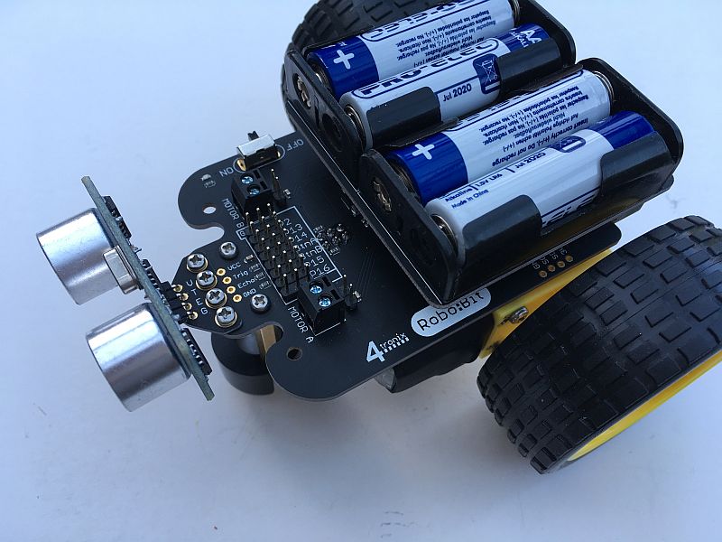 v2 Ultrasonic