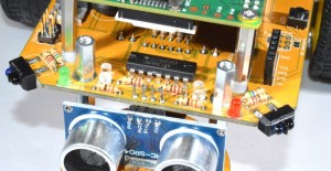
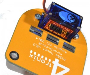
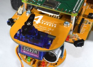
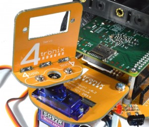
Pan & Tilt Kit for Pi2Go and Pi2Go-Lite
You can download a PDF of this guide from here
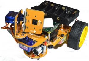
This system allows you to use the Pi Camera in 3 different ways with your Pi2Go or Pi2Go-Lite
- Fixed camera
- Camera with Pan control
- Camera with Pan and Tilt Control
All the parts are included in the kit for the complete Pan/Tilt assembly (except the Pi Camera which is an optional extra). You choose which system you want, and it is easy to change from one to another simply by undoing and replacing a few screws.
Step 1: Identify the Parts
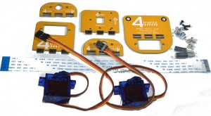
Included in the kit are the following parts:
- 1 x Base mounting plate
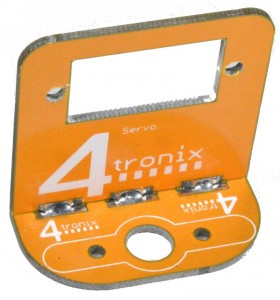
- 1 x Servo mounting plate
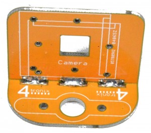
- 1 x Camera mounting plate
- 2 x Servo arm mounting plates
- 2 x Tower Pro SG92R carbon fibre micro servos
- 4 x M3 Self tapping 6mm screws (for attaching servo arms)
- 4 x M2.5 screws 6mm (for mounting the servos)
- 4 x M1.7 self-tapping screws 5mm (black, for mounting camera)
- 2 x M3 male-female pillars 12mm
- 1 x 200mm camera cable
Step 2: Solder the Camera Mount to a Servo Arm Plate
- Push the camera mount plate, with the camera markings on the inside as shown, into one of the servo arm plates
- Tack solder in one place
- Adjust the fitting until the camera mount is at right angles to the arm plate
- Solder all the other places on both sides for maximum strength (in fact there is very little weight, so only a couple of points need soldering if you’re in a hurry!)
Step 3: Solder the Tilt Servo Mount to a Servo Arm Plate
Make the tilt servo assembly in the same way as the camera mount assembly
Step 4: Attach the 12mm Pillars to the Pi2Go
One at a time, remove the existing screws that hold on the front caster assembly on and replace them with the 12mm pillars.
Keep the screws for use in Step 6
Screw on firmly.
Step 5: Attach the Pan Servo to the Base Mounting Plate
- Push the servo through the hole in the base mounting plate so the servo tabs are on the upper surface
- Use 2 of the 6mm M2.5 screws to screw directly into the mounting holes of the servo from underneath
Step 6: Fit the Base Mounting to the Pi2Go
Use the 2 screws you removed in step 4 to screw the base mounting plate
Attach the straight servo arm using the small screw in the servo bag. Fit it so that it runs front to back as shown, when the servo is in its middle position
Step 7: Fit the Tilt Servo Mount Assembly to the Pan Servo
Use 2 of the 6mm self-tapping screws provided. Do NOT use the 2 self-tapping screws in the servo bag as they are too long
The holes in the servo arm plate line up with the third hole out from the centre on each side of the servo arm.
Step 8: Fit the Tilt Servo into the Servo Mount
This time, push the servo in from the back of the board and screw in using the last 2 of the 6mm M2.5 screws
Attach the straight servo arm using the small screw in the servo bag. Fit it so that it runs top to bottom as shown, when the servo is in its middle position
Step 9: Fit the Camera to the Camera Mounting Plate
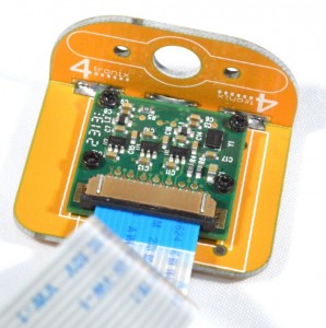
Use the 4 very small black self-tapping screws to mount the camera. DO NOT TIGHTEN the screws at all. Leave them loose or you will bend and damage the camera board
You can mount it in 2 positions, as shown on the silk screen. When used with both Pan and Tilt, we find it is best to mount it in the orientation shown above.
Fit the 200mm camera cable carefully into the camera connector
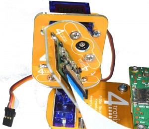
Step 10: Fit the Camera Assembly to the Tilt Servo Arm
Use 2 of the 6mm self-tapping screws provided. Do NOT use the 2 self-tapping screws in the servo bag as they are too long
The holes in the servo arm plate line up with the third hole out from the centre on each side of the servo arm.
You have now completed the assembly of the Pan Tilt mechanism.

